Table of Contents
Advertisement
Quick Links
Advertisement
Table of Contents

Subscribe to Our Youtube Channel
Summary of Contents for Dedrone RF-160
- Page 1 INSTALLATION Manual RF-160 ENGLISH IM-Inst-RF160en v0.4...
- Page 2 The declaration of conformity is available on request at support@dedrone.com. Copyright This manual is the intellectual property of Dedrone GmbH and is protected by copyright. All rights reserved. Dedrone GmbH Dedrone Holding, Inc.
-
Page 3: Table Of Contents
6.3 Cable Preparation for LAN connection ......................9 6.4 Install the Sensor ............................... 10 Integrate the RF-160 in your DroneTracker ................13 Integrate the RF-160 in your on prem DroneTracker Server ..............13 7.2 Integrate the RF-160 via Dedrone Cloud ...................... 15 Cleaning ............................16 Decommissioning ........................ -
Page 4: Safety
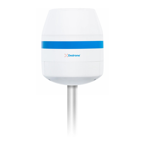
Action to resolve a problem 1.2 Intended Use The RF-160 is a passive, network-attached sensor for the detection of radio frequencies (RF). The RF-160 detects targeted radio signals of different drones and remote controllers and sends the data via mobile data or local network connection, along with an alert to the DroneTracker System. -
Page 5: Safety Information
When the RF-160 is plugged into an AC power source, there is always voltage applied to the internal electronics. Unplug the devices from the power source by disconnecting the AC cable and patch cable immediately. -
Page 6: The Rf-160
Dedrone Despite careful construction, electrical devices can cause fires. Do not mount the RF-160 in areas containing highly flammable materials or gases. Do not mount the RF-160 in a potentially explosive atmosphere. Do not install product near any heat sources such as radiators, heaters, exhaust air sys- tems or other equipment (including amplifiers) that produce heat. -
Page 7: Scope Of Delivery
5 Select the Mounting Place The position of the RF-160 has strong impact to the detection range. The RF-160 is intended for an installation on top of a pole. Make sure that a suitable pole is available (diameter between 1.2 in to 3.1 in (40 mm to 80 mm)). -
Page 8: Overvoltage Protection
Location Mounting Surface • Make sure the selected mounting surface is capable of supporting the combined weight of the RF-160 (12.2 lb (5.5 kg)) and the pole under all expected conditions of load, vibration, and tem- perature. Mounting Orientation •... -
Page 9: Installation
External Diameter 3.5 mm – 7.5 mm 6.3 Cable Preparation for LAN connection For a weather resistant connection to the RF-160, it is necessary to put on the supplied outdoor housing to the prewired RJ45 cordset. Procedure: Put the gland nut onto the cable. Thereby make sure that the thread shows to the plug. -
Page 10: Install The Sensor
Installation Dedrone Thread the connector body over the plug. The plug clicks in and gets fixed in the connector body. Slide the gland to the connector body and screw down the gland nut on the connector body. 6.4 Install the Sensor Desired mounting place fulfills the requirements (see chapter 5 Select the Mounting Place, page 7). - Page 11 Dedrone Installation Take out the pole mount. Put the pole mount on the pole. • To open up the pole mount unscrew the pole fixing screws. Adjust the pole mount in the desired directi- on and tighten the pole fixing screws approp- riately.
- Page 12 • Tighten the fixing screws appropriately. Only use the supplied screws. To connect the RF-160 to your local network, connect the patch cable with the outdoor housing to the network socket: • Remove the protective cap from the plug.
-
Page 13: Integrate The Rf-160 In Your Dronetracker
To connect to the RF-160 DHCP-Services are required that automatically assign an IP address to the RF-160. If the RF-160 and the DroneTracker Server are in the same Layer2 network they can be connected directly. If the RF-160 and the DroneTracker Server are in different networks refer to the Dedrone Planning Manual or consult your network administrator. - Page 14 The window Discovered Sensors appears. Select the desired RF-160 and choose [OK]. The RF-160 appears in the Site Explorer. To sort the RF-160 in the Site Explorer, drag and drop the element to the desired position. Choose [Save changes]. The window Site Configuration disappears.
-
Page 15: Integrate The Rf-160 Via Dedrone Cloud
Enter the registration key of your sensor and choose [OK]. The RF-160 appears in the Site Explorer. To sort the RF-160 in the Site Explorer, drag and drop the element to the desired position. Choose [Save changes]. The window Site Configuration disappears. -
Page 16: Cleaning
Dedrone 8 Cleaning Wrong cleaner damages the housing The wrong cleaner can damage the housing or antenna of the RF-160. Never use glass cleaner or other solvent cleaner to clean the RF-160. • Use solvent-free cleaner to clean the RF-160. -
Page 17: Technical Data
AC 100-240V 50/60 Hz max. 1 A or PoE+ IEEE 802.3at (25 W) Connectivity Via LAN to existing IT infrastructure or via the integrated mobile connection in the Dedrone Cloud Configuration, Operation, and Via DroneTracker software (software version >= 4.1 and valid Alarms... - Page 18 AIRSPACE SECURITY SOLUTION Dedrone Holding, Inc. Dedrone GmbH +1 415 813-6116 220 Sansome Street Miramstraße 87 +49 561 8617990 San Francisco, CA 94104 34123 Kassel info@dedrone.com Germany www.dedrone.com...


Need help?
Do you have a question about the RF-160 and is the answer not in the manual?
Questions and answers