
Related Manuals for Mechanics & Electronics ME2000-V

Summary of Contents for Mechanics & Electronics ME2000-V
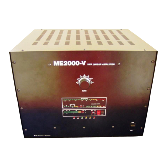
- Page 1 ME2000-V 2M LINEAR AMPLIFIER 19’’ BOX GS35B Mechanics & Electronics Inc. Hungary Draskovits Gábor HA1YA Szombathely, Kárpáti K. u. 43. H-9700 e-mail ha1ya@chello.hu ha1ya@w-nets.hu...
-
Page 2: Table Of Contents
C O N T E N T 1.0 General overview..............2 2.0 Specifications ..............4 3.0 Technical description............5 3./a Front Panel................6 3./b Rear Panel................8 4.0 Installation ................9 5.0 Troubleshooting ..............10 6.0 Drawings ................13... -
Page 3: General Overview
UHF amateur bands with similar mechanical measures and appearance ,using ceramic v alves easily available on the market. The ME2000-V utilise the advantages of the ceramic valve, and considering the power output and price, is a worthy competitor of similar equipment on the market. - Page 4 1.5 The PA is constructed with the following protection circuits and useful features: Heat up time checking circuit (3 min) Protection circuits (Ia, Ig1, temperature, SWR>3,overdrive) Cooling fans (2 pcs) Function and status indicator LEDs (6 pcs) 4KVA transformer OPTO coupled PTT switch Built in I/O coax relays External HV power supply...
-
Page 5: Specifications
2.0 S P E C I F I C A T I O N S ME2000-V Frequency coverage 144-146MHz Operating modes ALL mode Output Power 2000 W pep CW/SSB Driving Power 0-120W MAX Input VSWR max 1:1.5 In/Out impedance 50 Ohm... -
Page 6: Technical Description
RF radiation. RF radiation will decrase output power and can cause self oscillation of the transmitter chain as well as a health risk. We can build normal 19’’ “box” version the line ME2000-V. 2. INPUT CIRCUIT Tube is driven in catode over T filter. -
Page 7: Front Panel
3/a FRONT PANEL POWER ON Main switch of the equipment is on the power supply (ME3000-S). 2. ON LED The LED indicator glows when the Linear is switched on. Doesn’t lit in case the 15V DC – supply for the protection circuits and antenna switch - is missing. 3. - Page 8 10. FWD Output power indication. Use for tuning the Linear. The indication calibrated for 50 ohm aerial impedance. At other values the accuracy may be +- 10%. 11. REV Will indicate the relative reflected power on the right side meter. Helps to check the aerial.
-
Page 9: Rear Panel
3/b REAR PANEL 1. Remote connector Connecting with short cable to ME3000-S power supply. 2. FAN 1 Cooling fan for the RF tube (230V/AC) 3. PTT Connection for PTT RCA. The relays are closed by earth connection. Low voltage, low current opto entry. Fit for open collector control a well (24V 10mA). 5. -
Page 10: Installation
4.0 INSTALLATION 4.1 Connect your TCVR to the Linear using a short, 50 Ohm coaxial cable. 4.2 Connect your TCVR ground giving socket to the PTT RCA socket on the rear panel of the Linear, using a screened cable. In case your TCVR has an open collector PA controller output, you can use it without difficulties. -
Page 11: Troubleshooting
5.0 TROUBLESHOOTING Malfunctions are mostly due to improper handling, overload or similar reason. 5.1 Do not use higher input power as stated in the specification. The grid protector circuit will usually safe the power valves, but OVERLOAD alarm will appear regularly. - Page 12 5.5 LIMITED WARRANTY The M+E Mechanics & Electronics will warrant that the equipment will perform substantially in accordance with the written materials for a period of 12 month from the date of receipt and will be free from defects in material and workmanship under normal use.
- Page 13 5.7 SAFETY INTERLOCK SWITCH While the Amplifier's top cover is in place, the interlock switch closes to allow AC line voltage to reach the power transformer. When the top cover is removed, the interlock switch opens and disconnects the line voltage. This does not discharge the bank of power supply filter capacitors.
Need help?
Do you have a question about the ME2000-V and is the answer not in the manual?
Questions and answers