
Related Manuals for Synergy Global Technology LCD1U17-35

Summary of Contents for Synergy Global Technology LCD1U17-35
- Page 1 Toll Free: 1-888-865-6888 Tel: 510-226-8368 Fax: 510-226-8968 Email: sales@RackmountMart.com...
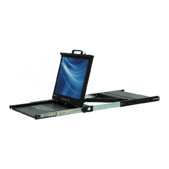
- Page 2 LCD1U17-35 17.3” Full HD LED Backlignt Single Rail Console with Modular KVM Switch User Manual Rev 1.0...
- Page 3 Packing List The complete LCD1U17-35 17.3” Full HD single rail console with modular KVM switch package consist of : One 1U 19” rack mount console Two rails with front and rear bracket Two extended brackets Two Short brackets ...
-
Page 4: Safety Instructions
Safety Instructions 1. Please read these safety instructions carefully. 2. Please keep this User’s Manual for later reference. 3. Please disconnect this equipment from AC outlet before cleaning. Don’t use liquid or sprayed detergent for cleaning. Use moisture sheet or clothe for cleaning. - Page 5 The equipment has dropped and damaged. If the equipment has obvious signs or breakage. www.RackmountMart.com...
-
Page 6: Table Of Contents
2.8 Recall ....................9 2.9 Volume ....................10 2.10 Exit ....................10 3. Installation ....................11 3.1 Install LCD1U17-35 into Cabinet ............11 3.1.1 Notes ..................11 3.1.2 Hardware Kits Contents ............11 3.1.3 Step A (Install Console) ............12 3.1.4 Step B (Replace short bracket).......... - Page 7 3.5 Fingerprint Scanner ................23 3.6 Turning on the Console ............... 23 3.7 Testing the Console ................23 4. KVM Switch ....................24 www.RackmountMart.com...
-
Page 8: General Information
1. General Information LCD1U17-35 Full-HD Patented Single Rail console industrial level input solution to optimize your space utilization by controlling your systems in just 1U. With the unique modular design, you can easily integrate more than 24 models of KVM switches with different functions and expand the connections up to 8 levels of the KVM switches. -
Page 9: Advantage
KVM switch modules by air. 1.3 Advantage Easy to install: With the unique separate rail design. One man can install the LCD1U17-35 console easily. In case you need to maintain the console, you can easily uninstall without effecting the server above or below. -
Page 10: Product Specification
1.4 Product Specification 1.4.1 LCD1U17-35 Model name LCD1U17-35 Number of ports Dimension 582 x 436.4 x 44.0 mm / 20.8 x 17.2 x 1.7 inches Net Weight 13 Kg / 28.7 lbs Display Size 17.3 inches Full HD Panel Type... -
Page 11: Lcd1U17-35 I/O Diagram
Figure 1-2. LCD1U17-35 Dimension 1.4.2 LCD1U17-35 I/O Diagram Figure 1-3. LCD1U17-35 Front View Share and Store Function A. Front USB port 1 (optional) B. Front USB port 2 (optional) 3 4 5 6 7 8 9 Figure 1-4. LCD1U17-35 Rear View 7. -
Page 12: Panel Controls And Osd Function
“Enter” button. GERRN Power STANDBY Indicator SUSPEND Table 2-1. Panel Controls Figure 2-1. LCD1U17-35 OSD Control Bar 2.1 Input Source 1. Press the “menu” button. 2. Use the “Down” and “Up” button to scroll. Input Source Auto tune. Brightness... -
Page 13: Auto Tune
3. Press the“menu”button to enter,and you will see: HDMI AUTOSERCH 4. Use the “Down” and “Up” button to select the input source of signal. 5. Press the “menu” button to enter 2.2 Auto Tune Press the “auto tune” button. The panel will adjust the display size automatically and also tune the panel to its best condition. -
Page 14: Color
Auto tune. Brightness Contrast Color Position Language Recall Volume Exit 1. Press the “menu” button to enter. 2. Use the “Down” and “Up” button to adjust the contrast of the display. 3. Press the “menu” button to enter. 2.5 Color 1. -
Page 15: Position
4. Use the “Down” and “Up” button to adjust the color of the display. 5. Press “menu” to enter. 2.6 Position 1. Press the “menu” button. 2. Use the “Down” and “Up” button to scroll. Input Source Auto tune. Brightness Contrast Color Position... -
Page 16: Recall
Contrast Color Position Language Recall Volume Exit 3. Press the “menu” button to enter. And you will see: English Deutsch Francais Italiano Espanol 4. Use the “Down” and “Up” button to scroll. 5. Press the “menu” button to enter. 2.8 Recall 1. -
Page 17: Volume
2.9 Volume For Audio version use. 2.10 Exit Press the “exit” button to quit OSD menu. www.RackmountMart.com... -
Page 18: Installation
3. Installation 3.1 Install LCD1U17-35 into Cabinet 3.1.1 Notes 1. Please check all peripherals according the list before installation. To make sure that the whole unit was not damaged and lost during shipping process. If you encounter any problem, please contact your dealer. -
Page 19: Step A (Install Console)
3. Short bracket x 2 4. Bracket attachment x 2 LCD1U17-35 bracket attachment 5. Screw (length = 6 mm) x 6 6. Screw x 6 7. Key x 2 3.1.3 Step A (Install Console) 1. Adjust rail until two screws appear. - Page 20 3. Adjust rail to fit your cabinet 4. Install front and rear bracket on cabinet. 5. Tight seven screws up. 6. Repeat step 1~5 for the other side. 7. Push console into rails. (Be careful rear box loose when take out console from carton.) www.RackmountMart.com...
-
Page 21: Step B (Replace Short Bracket)
8. Unlock and pull rail–lock switch (left and right at the same time) then push console to the end. lock unlock rail-lock switch 9. Install three screws (length = 6 mm) in rear of the console. (Both sides) 10. Finish installation as below. 3.1.4 Step B (Replace short bracket) 1. - Page 22 2. Take two original brackets out. original bracket original bracket 3. Put short bracket to rear of the rail. short bracket 4. Install four screws (don’t tight-up) to combine rail, short bracket and bracket attachment. bracket attachment short bracket 5. Repeat step 1 ~ 4 for the other side. 6.
-
Page 23: Step C (Replace Extended Bracket)
3.1.5 Step C (Replace extended bracket): 1. Loose (Not remove) seven screws. 2. Release six screws. 3. Take rear bracket out. original bracket 4. Adjust rail and input extended bracket to rear of the rail then adjust extended bracket to fit your cabinet. Install unless 2~3 screws (don’t tight-up) upon the length you need. -
Page 24: Unload Steps
3.1.6 Unload Steps 1. Make sure the console has locked and turned off. 2. Loose two thumb screws and pull modular KVM switch out. 3. Release three screws in rear of the console. (Both sides) 4. Unlock. 5. Pull console out until console lock. www.RackmountMart.com... - Page 25 6. Pull rail-release switch and pull console out.(Both sides. Be careful when pull out console.) rail-release switch 7. Push rail-lock switch on the rail and push rail back. (Both sides) rail-lock switch on the rail www.RackmountMart.com...
-
Page 26: Install Modular Kvm Switch
3.3 Install Modular KVM Switch 3.3.1 Hardware Kits Contents 1. Bracket with thumb screw x 2 2. Screw (length = 6 mm) x 4 3.3.2 Install Modular KVM Switch Step 1. Install two screws (length = 6 mm) to combine bracket and KVM switch. (Both sides) www.RackmountMart.com... - Page 27 2. Push KVM switch into the rails from rear of cabinet. plastic rail of KVM switch rear view of rail 3. Tight thumb screw of bracket up to fix KVM switch in console and finish installation. (Both sides) www.RackmountMart.com...
-
Page 28: Installing The Video Card And Video Driver
3.4 Installing the Video Card and Video Driver Before connecting the LCD console, make sure your computer has a video card already installed for the panel. After you connect the console, install the video software driver. The video driver is supplied by the video card manufacturer and may be found on the CD-ROM that came with your computer. -
Page 29: Connecting The Console
3.4.2 Connecting the Console To connect an LCD console to a computer, perform the following steps PS/2-USB switch Figure 3-1. The Rear View of LCD Console 1. Turn off your computer. You should always turn off your computer before connecting or disconnecting a device. 2. - Page 30 PS/2 ports on the rear panel of your computer. Or you can use USB interface to connect your computer. ( Use PS/2-USB switch to select your interface. The switch has to be on PS/2 side when you use PS/2 interface connector.) 4.
- Page 31 1. Power up the console, and then turn on your computer. 2. Make sure the video image is centered within the screen area. Use the OSD controls to adjust the image (see note below) or press the Auto button on the left or underneath of the panel.
Need help?
Do you have a question about the LCD1U17-35 and is the answer not in the manual?
Questions and answers