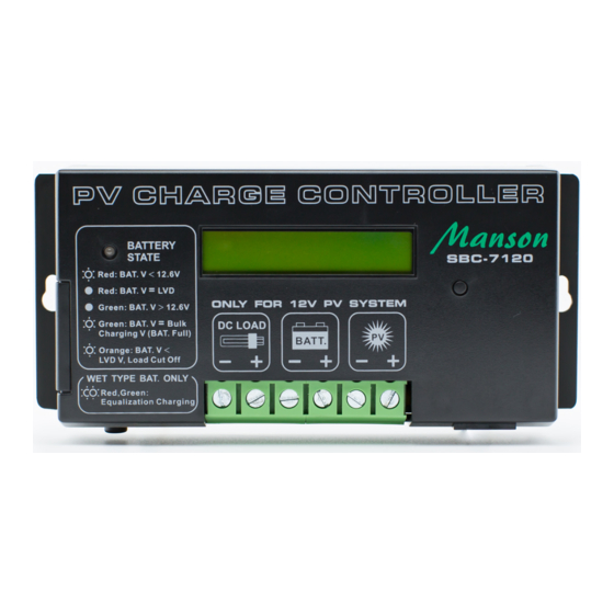
Summary of Contents for Manson Engineering Industrial SBC-7230
-
Page 1: Table Of Contents
PV Charge Controller SBC-7230 User's Manual Table of Contents Precautions and Specifications 1. Introduction 2. Control and Indicator 3. Installation and Indication 3.1 Connection 3.2 LED Indicator 3.3 LCD Display 3.3.1 LCD Display Sequence 3.4 The Dip Switch, Set-Buttons and Reset Button Functions 3.4.1 Adjust the PV Charge Controller Settings... - Page 2 Cover wrench handles with plastic tape or vinyl dip coating material. Specifications Models SBC-7230 Battery voltage Maximum PV panel open circuit voltage Continuous load/charge current Maximum charge current (5 mins)
-
Page 3: Introduction
Introduction The SBC-7230 PV Charge Controller is designed for use with all types of 24V photovoltaic(PV) panels/systems and different types of 24V batteries, such as wet or sealed lead acid, lead calcium, lead antimony battery. Numerous features are provided to maximize the performance of the system: ●... -
Page 4: Installation And Indication
This controller has Electronic Blocking feature, therefore, it is not necessary to connect a diode between the PV module and the Controller. The recommended wire size is #10AWG(SBC-7230). It is recommended that the PV Charge Controller should be installed in a dry, sheltered location away from sources of high temperature and moisture. -
Page 5: Lcd Display
LCD Display The LCD Display shows the battery voltage, PV panel voltage and the charging modes during normal day time operation. At night time or low sunlight or PV disconnected situation, display of PV VOLT value is to be ignored . LCD DISPLAY Descriptions BATT VOLT.... -
Page 6: The Dip Switch, Set-Buttons And Reset Button Functions
The Dip Switch , Set-Button and Reset button functions The dip switch, set buttons and reset button are used for adjusting the PV Charge Controller Settings (see Section 3.4.1 and 3.4.2) ( * Open the Side door, you can see the dip switch & set buttons.) 3.4.1 Adjust the PV Charge Controller Settings Figure 4 Figure 5... -
Page 7: Select The Auto/Manual Equalization Charging And Night-Light Mode
Figure 6 Adjustable parameters in Setting Mode 3.4.2 Select the auto- equalization charging and night-light mode The dip switch 1 is for Night-Light Mode , switch 2 for Equalization Charging mode and switch 3 is always set at off position THE PV CHARGE CONTROLLER IS FACTORY PRESET FOR USE WITH SEAL TYPE BATTERY THAT IS : NO AUTO EQUILIZATION CHARGING BECAUSE DIP SWITCH 2 IS AT ON POSITION. -
Page 8: Pv Charge Control Mode
PV Charge Control Mode The SBC-7230 PV Charge Controller can operate in the several modes. This includes the 3-stage Charge Control, Equalization Charging Mode, DC Load Control Mode, NIGHT-LIGHT mode, Temperature Sensing and Over Temperature Protection features. 4.1 3-Stage Charge Control The main function of charge controller is to regulate the flow of electricity from the photovoltaic panels to the batteries. -
Page 9: Equalization Charging Mode (Automatic Or Manual)
4.2 Equalization Charging Mode (Automatic or Manual) WARNING: Equalization Charging is only for Wet-type Lead Acid Battery. The Equalization Charging Voltage is factory pre-set to the Bulk Voltage + 1 Volt. The battery manufacturer should be consulted. Clean, distilled water will need to be added to the battery AFTER the equalization process. - Page 10 When the battery voltage becomes higher than Low Voltage Reconnect (LVR) setting for 5 minutes, the controller will automatically reconnect the load again. The following chart shows the night light mode selections. LCD Display Explanation SUNSET NIGHT SUNRISE 2 HR ON 2 HOURS ON 4 HR ON 4 HOURS ON...
-
Page 11: Temperature Sensor (Optional)
Each of the 10 night-light mode options has a unique number of flashes. These are as follows: Switch Setting # of Flashes 2 Hours On 4 Hours On 6 Hours On 8 Hours On 10 Hours On 3 / OFF / 1 4 / OFF / 2 6 / OFF /2 Dusk to Dawn... - Page 12 Activate the feature Please follow the steps below: 1. Open the case of the controller, there should be a small control board near the Remote Signal Terminal as shown in figure 6. Figure 8 2. On the small control board, there is a sky blue color dip switch.


Need help?
Do you have a question about the SBC-7230 and is the answer not in the manual?
Questions and answers