
Subscribe to Our Youtube Channel
Related Manuals for IPX DDK-1801BC

Summary of Contents for IPX DDK-1801BC
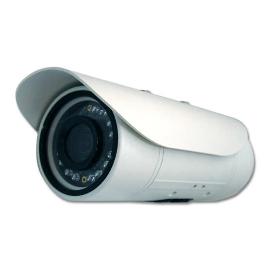
- Page 1 INSTALLATION & OPERATION MANUAL DDK-1801BC Fixed Indoor/Outdoor IP Bullet Camera (AF Lens)
-
Page 2: Table Of Contents
PDATING YSTEM OFTWARE 3. Network Configuration ................13 3.1 C ................13 ABLE ONNECTIONS 3.1.1 DDK-1801BC to Computer connection ................13 3.1.2 DDK-1801BC to Network Switch (INTRANET)............13 3.2 N ..........14 ETWORK ETTINGS ONFIGURATION 3.2.1 Enabling DHCP Function ....................14 3.2.2 Setting an IP Address.......................14 3.3 TCP/IP C... - Page 3 4.1.3 Setup ..........................26 5. ADVANCED OPERATION ..............76 6. SPECIFICATIONS...................79 7. Client System Requirements..............81 APPENDIX 1. –How to run DDK-1801BC UPnP ........82 APPENDIX 2. –Register as a DDNS member ..........92...
-
Page 4: Safety Precautions
Do not block ventilation openings. Never spill liquid of any kind on the camera Do not attempt to service the DDK-1801BC yourself. Opening the DDK-1801BC’s enclosure may expose the user to electrical shock. Please refer all servicing to your reseller. -
Page 6: Description
1. DESCRIPTION 1.1 PHYSICAL DESCRIPTION Internal View SCREWS SUN SHIELD SD PCB LENS FAN REAR CASE MIDDLE CASE POWER PCB WATERPROOF RUBBER SENSOR PCB PCB PLATE IR PCB FRONT CASE External View NOTE: Use the 2 provided screws to attach the sun shield (above) into the 2 extreme holes shown in the picture below to get an unobstructed viewing angle. - Page 7 VIDEO OUT Connector: Connector providing composite video output. AUDIO IN: Connector to receive audio input from external devices. USB port: Connects DDK-1801BC to a USB port on a computer. AUDIO OUT: Provides audio to an external device. SD/ SDHC CARD slot: Used for updating system software and archiving video.
-
Page 8: The Reset Button
1.2 The Reset Button The Reset Button will bring the DDK-1801BC back to its factory default settings. Press the Reset Button for about 10 seconds. A Blue screen will be displayed and a text that says “RESETTING…” will appear. The device will then auto reboot. All settings will then be back to default. The following items will return back to default. -
Page 9: Alarm Wiring Diagram
1.3 Alarm wiring diagram DDK-1801BC +12V +12V... -
Page 10: The Usb Function
1. Using an SD card as a card reader. Insert an SD card into the DDK-1801BC and then connect to the PC. You may then transfer files between the SD card and the PC. Once you've connected your DDK-1801BC to your computer Windows will detect the connection and ask you what you want to do with the SD card. -
Page 11: Installation
If the user decides to remove the DDK-1801BC cover after more than a few months of use, the used desiccant pack should be removed and place a replacement pack inside the camera. -
Page 12: Updating System Software
Verify the version of the system software. WARNING If the power of the DDK-1801BC is suddenly lost in step 7, remove the SD card first and then power the camera on. If the DDK-1801BC operates normally repeat step 3. Otherwise contact the manufacturer. -
Page 13: Network Configuration
Hub/Switch Wiring Configuration Straight Through PC Wiring Configuration 3.1.1 DDK-1801BC to Computer connection LAN CAMERA CROSSOVER CABLE RJ-45 TO PC LAN CARD CROSSOVER CABLE PIN CONFIGURATION 3.1.2 DDK-1801BC to Network Switch (INTRANET) TO PC NETWORK CARD LAN CAMERA RJ-45 uplink... -
Page 14: Network Settings Configuration
192.168.1.1 Therefore, if the connected network is identified as Class C, for example, the first three sets of numbers of the DDK-1801BC IP address must be the same as the network address. If the connected network is identified as Class B, the first two sets of numbers of the DDK-1801BC IP address must be the same as the network address. -
Page 15: Tcp/Ip Communication Software
3.3 TCP/IP Communication Software Follow the procedure below to install the TCP/IP communication program on your computer. Click Start, and then click Control Panel. Double click the Network Connections icon 3. Right-click your network connection and then click Properties. - Page 16 4. On the General tab, check if the Internet Protocol (TCP/IP) is included in the list. If the TCP/IP is included, proceed to section 3.5. If it is not included, please follow section 3.4 to install the TCP/IP.
-
Page 17: Tcp/Ip Installation
3.4 TCP/IP Installation On the General tab of Connection Properties, under “This connection uses the following items”, click Internet Protocol (TCP/IP). Then click Install. Select Protocol from the network component type then click Add. Select Microsoft TCP/IP from the network protocol then click OK. Click Close to return to the Network Connections window. -
Page 18: Tcp/Ip Configuration Setting
If you are using a DHCP server, select Obtain an IP address automatically. Any assigned IP address for the connected DDK-1801BC must be in the same class type as the server. If there is no DHCP server, please select specify an IP address and enter the IP address, subnet mask and default gateway of your choosing to your PC. -
Page 19: Connection Testing
Click Start > All Programs > Command Prompt. Enter ping XXX.XXX.XXX.XXX (the DDK-1801BC’s IP address), then enter. (See the sample screen below). ** This is the IP address for a DDK-1801BC that is assigned for the connected camera. - Page 20 If you receive a response as in the screen below, the connection hasn’t been successfully established. Please re-check all the hardware and software installations by repeating sections 3.4 and 3.5. If you still can’t establish the connection after rechecking, please contact your dealer.
-
Page 21: Operating Instructions For Network Connection
4. Operating Instructions for Network Connection The DDK-1801BC may be accessed through a Web Brower. RJ-45 PIN configuration for Ethernet PIN Assignment PIN NO. RJ-45 socket TX + TX - RX + 1 2 3 4 5 6 7 8... -
Page 22: Web Browser
Start up your Web Browser, and then follow the steps below to connect the DDK-1801BC. Click on the URL box at the top of the window. Enter the URL address of the DDK-1801BC into the URL box and press the “Enter” key to enter the home page. -
Page 23: Live Video
4.1.2 Live Video Live video from the DDK-1801BC is displayed on the home page when your Camera is present in your browser. Additional settings are provided on the home page. AJAX (default) and the ActiveX viewer types display different formats on the home page. - Page 24 ActiveX viewer: Select from the thumbnail options for taking snapshots, setting-up a Storage Folder, selecting Full Screen mode, Recording, Listening, Talking and Zooming. Snapshot: Click the button to take a snapshot. The icon will change to a blue color when working properly. Set Storage Path: Click on the button to set a storage folder for saving snapshots and video clips.
- Page 25 EPTZ Digital Zoom mode. This mode utilizes the megapixel resolution of the DDK-1801BC to simulate the functions of a mechanical PTZ camera. When the digital zoom mode is active, the image can be zoomed in and out.
- Page 26 IP address. The DDK-1801BC’s default IP is 192.168.1.168. You can set an IP address for the DDK-1801BC if the LAN unit isn’t connected to a DHCP server. Or use DHCP protocol if DHCP is supported on your LAN. The DDK-1801BC will obtain an IP address automatically from the DHCP server.
- Page 27 Step 2: If using PPPoE, select Enable and enter user name and password. Otherwise select Disable and click Next to continue. Step 3: If using a Dynamic DNS account, select Enable and enter your host information. Click Next to continue.
- Page 28 Click Next to continue. Step 6: If DHCP is selected, a summary of the DDK-1801BC’s settings will be displayed. Write down all this information as it is needed to access the camera over the network. Click Apply to save settings.
- Page 29 4.1.3.2 Changing Image Settings Follow the steps below to change the cameras video settings. A preview of the image will be shown in the Live Video window. . Click Submit to activate and save changes. The Image Setup setting page 1.
- Page 30 “Flip”, “White Balance”, “Brightness”, “Contrast”, “Saturation” and “Sharpness”. 4. DEVICE SETTINGS. Includes “Device Name” and “Timestamp”. • Click “Enable OSD” and checkmark the box to activate this function. • Enter "Timestamp Label". • Enter "Timestamp Location". 5. Click the Submit button to submit new image settings Functions: The metering method determines the exposure.
- Page 31 Reverses image display. Mirror: To flip the DDK-1801BC’s image 180 degrees. Flip: White balance corrects unnatural color shades. Select your options from White Balance “Auto”, “Outdoor”, “Indoor”, “Fluorescent” and “Push Hold”. Setting to compensate for backlighting. Brightness: Controls color intensity/strength.
- Page 32 The Audio and Video setting page 1. Click on the Audio and Video button to enter the Audio and Video settings page. Here you may configure multiple video profiles with different settings. Click Submit to save your changes. 2. Select the Profile Number from 1-3. Then set the Aspect ratio of 4:3 or 16:9. Click Save to activate it.
- Page 33 4. Set the details of the audio functions. 5. Select 50 Hz or 60Hz Power. 6. Click on the Submit button to save settings. Functions: Select the Profile Number from 1-3 and the default video profile Profile Number number is 2. The aspect ratio of an image is the ratio of the width of the image to its Aspect ratio height.
- Page 34 Follow the steps. Connect DDK-1801BC through browser. Ensure “Audio Mechanism Setting” & “Enable audio out” are both selected. Click Submit. Connect Mic to the PC, and connect the DDK-1801BC Audio out to the speaker. Select “Talk” ; speak to the PC-connected microphone.
- Page 35 The Lens Control page Select Lens Control to enter the Lens Control setting page. Use the focal length (zoom function) and the focus control (focus function) to optimize the remote focus adjustment. Select the Focus Mode: the Manual or the Auto mode. Select Auto to enable the autofocus and motorized zoom.
- Page 36 The Privacy Mask settings page Click on the Privacy Mask button to enter the Privacy Mask Area setting page. Mask up to 3 privacy areas on the displayed video to specify the areas on the DDK-1801BC's image to be blocked/excluded from recordings and snapshots.
- Page 37 Enable this setting to allow your DDK-1801BC to be configured Enable UPnP Presentation: as a UPnP device on your network. Enable UPnP port forwarding: Enable this setting to allow the DDK-1801BC to add port forwarding entries into your router automatically.
- Page 38 Internet Service Provider. If the DDK-1801BC is behind a router or a gateway you do not need to configure this setting.
- Page 39 Enter the “RSTP port” and the “Access name for stream” for the MJPEG or JPEG streams. Click the Submit button to save the new settings. NOTE: To use an RTSP player to access the DDK-1801BC, use the following RTSP URL command to request transmission of the streaming data.
- Page 40 Functions HTTP ports allow you to connect to the DDK-1801BC via a standard web HTTP Port browser. This port can be set to a number other than the default HTTP port 80. A corresponding port must be opened on the router. For example, if the port is changed to 8080, users must type in the web browser 'http://192.168.0.100:8080'...
- Page 41 Changing the Network Settings —Network Traffic. The “Network” page has a “Traffic” icon at the upper left. Specifying the maximum download/upload bandwidth for each socket is useful when connecting your device to a busy or heavily loaded network. Please follow the steps below to change the setting through the network. 1.
- Page 42 Changing the Network Settings — DDNS. The DDNS (Dynamic Domain Name Server) will use a DNS host name and synchronize it with the public IP address of the router when it changes. A user name and password are required when using a DDNS service.
- Page 43 Functions Check to activate this function. Enable DDNS Function: (The Domain Name System) is an Internet service that translates domain names into IP addresses (i.e. 192.168.0.20). The address can be obtained from your ISP or network gateway. Select your Dynamic DNS provider from the pull down menu or enter the Server Address: server address manually.
- Page 44 Changing the Network Settings — HTTPS. Click the “HTTPS” icon at the upper left of the “Network” page. Follow the steps below to change the HTTPS setting. Click on the HTTPS button on the upper left menu to enter the “HTTPS Setting” page. Select the “Enable HTTPS secure connection”...
- Page 45 (5) The pop-up windows will show a certificate request. (6) Look for a trusted certificate authority that issues digital certificates. Enroll the DDK-1801BC. Wait for the certificate authority to issue a SSL certificate; click “Browse...” to search for the issued certificate and then click “Upload”...
- Page 46 Allow List: The starting IP Address of the devices (such as a computer) which have Start IP Address permission to access the DDK-1801BC. The ending IP Address of the devices (such as a computer) which have End IP Address permission to access the DDK-1801BC.
- Page 47 Deny List: The starting IP Address of the devices (such as a computer) which don’t Start IP Address have permission to access the DDK-1801BC. The ending IP Address of the devices (such as a computer) which don’t End IP Address have permission to access the DDK-1801BC.
- Page 48 1. Click on the System button to enter the “Time and Date” page (default). In this area you may automatically or manually configure, update, and maintain the internal system clock of the DDK-1801BC. 2. To set the Time Configuration select a time zone from the drop-down menu. Select Enable Daylight Saving Time if required.
- Page 49 Functions: Select time zone from the drop-down menu. Time Zone: Select to enable daylight saving time. Enable Daylight Saving: Select this option to configure Daylight Saving setting Auto Daylight Saving: automatically. Select this option to configure Daylight Saving date and Set date and time manually: time manually.
- Page 50 Changing the System Settings — Digital Input &Output. 1. Click on the DI and DO button on the left side of the “System” page to enter the “DI and DO” page. 2. Select the active state of the Digital Input 1 from the drop-down list. 3.
- Page 51 Changing the System Settings — ICR. Follow the steps below to change the IR cut filter function settings. Click on the ICR button on the left side of the “System” page to enter the “ICR” page. Select option for “IR-Cut Removable filter trigger condition”: “Automatic”, “Day Mode”, “Night Mode” or “Schedule”.
- Page 52 Changing the System Settings — Users. Click the Users button on the left side of the “System” page to enter the “Users” page. Add, modify or delete a user’s data. Click Add/ Modify User button to save new user settings. Click the Home button to return to the home page.
- Page 53 Click “Restore Factory Defaults” to restore factory defaults. You may Restore Factory Defaults: browse and load saved configuration files to restore saved settings Click “Reboot Device” to reboot the device. This option will restart the Reboot Device: DDK-1801BC.
- Page 54 Click the “Browse…” button to find and select the UPDATE.BIN file which was saved to computer Click the “Upload” button. NOTE: DO NOT power off DDK-1801BC while updating firmware. NOTE: Don’t interrupt the process while the unit is updating. NOTE: Updating with the wrong UPDATE.BIN file may cause physical damage to the device.
- Page 55 4.1.3.5 Changing the Application Settings Changing the Application Settings —Language Setting. Click on the Language button on the left side to enter the “Language Settings” page. Select language and click "Submit" to save.
- Page 56 Changing the Application Settings —Motion Detection. Setting motion detection: Click the Motion Detection button on the left side of the Application page to enter the “Motion Detection” page. Drag the mouse across a targeted zone to draw a rectangle on the image. NOTE: You can set more than one targeted zone.
- Page 57 Changing the Application Settings —Event. Click the Event bottom at left of Application page and then click on “Add” to enter the setting pages for the Server, Media, Event and Recording settings. Click “Delete” to erase settings. The Event Setup page has 4 sections: Server, Media, Event, and Recording. To add a new setting click add under EVENT, SERVER, or MEDIA To delete a setting from a drop-down click Delete.
- Page 58 Server: Click the Add button in the Server area to enter the “Server” settings page. Enter the unique Server name. There are four types of servers supported: email server, FTP server, HTTP server and network storage. Set Email the details. "Sender email address", the email address of the sender. "Recipient email address", the email address of the recipient.
- Page 59 for uploading. "Passive Mode": Set details for Network storage. Only one network storage device is supported. "Network storage location" is the path to upload the media. "Workgroup" is the workgroup for network storage. Click on SD card to activate this function. The SD card is used for recording video data. Click “Submit”...
- Page 60 Password: Enter the password of the FTP account. Remote folder name: Enter the folder name where the media file will be sent. If the folder name does not exit the DDK-1801BC will create one on the FTP server. Passive mode: Most firewalls do not accept new connections initiated from external requests.
- Page 61 Delete. Note that only when the server setting is not being applied to an event setting (Application> Event> Event> The “Action” option) can it be deleted or the DDK-1801BC won’t take any action when a trigger is activated.
- Page 62 Media: Click the Add button in the Media area to enter the “Media” settings page. Enter the unique Media name. There are three types of supported media: snapshot, video clip and system log. Set details of the Snapshot. "Source": Select the video source. "Send Pre-event images": The number of pre-event images.
- Page 63 Snapshot: Source: Select to take snapshots from the video profile. Send pre-event image(s) [0~4]: The DDK-1801BC has a buffer area; it temporarily holds data up to a certain limit. Enter the number of how many images to be captured before a trigger is activated. Up to 4 images can be generated.
- Page 64 100 seconds can be set. Example: If pre-event recording is set to 4 seconds and the maximum duration is set to 10 seconds, the DDK-1801BC continues to record for another 5 seconds after a trigger is activated. 1 sec.
- Page 65 System log: Select to send a system log when a trigger is activated. Click Submit to activate the setting. Click Submit to enable the settings and exit the page. The new media settings will appear on the Event Settings page. NOTE: To remove a media setting from the list (Application>...
- Page 66 Event: Click the Add button in the Event area to enter the “Event” settings page. Enter an Event name. Check the “Enable this event” box to activate this function. Then set the Priority and the Source from the drop-down list. "Priority": The event with higher priority will be executed first.
- Page 67 An event is the action initiated by the user-defined trigger source. Set the event details for each as follows. Trigger: This option defines when to trigger the DDK-1801BC. The trigger source can be configured to use the DDK-1801BC’s built-in motion detection, periodic,...
- Page 68 Select the days of the week. Set the recording schedule in the 24-hour time format. Action: Define the actions to be performed by the DDK-1801BC when a trigger is activated. Trigger D/O for ~ seconds: Select this option to turn on the external digital output device when a trigger is activated.
- Page 69 Set the recording schedule time. Select the day(s) for recording to be enabled Select Always or From. "Always": This enables the DDK-1801BC to make video clips continuously. "From": The time range specified for the video clip. Click “Submit” to save or click “Don’t Submit” to go back to the Event main page.
- Page 70 Record settings: Click Add in the Record area on the Event Settings page to open the Record settings page. In this page recording source, recording schedule and recording capacity can be defined. A total of 2 recording settings can be configured. Enter the Record entry name for the event setting.
- Page 71 4.1.3.6 Changing the Storage Settings Changing the SD card Settings. Click the “storage” button at the top of the Setup page to enter the “SD Card” screen. The SD Card page contains two image modes: Video and Picture. Click “Video” or “Picture” to enter the sub year-month folder. Click to enter sub date folder.
- Page 72 4.1.3.7 Status Device information. This page displays information about device and network connection. Click the “Device info” button on the Status page to enter the “Device info” screen.
- Page 73 Device information. This page displays the DDK-1801BC log information. Click the “Device info” button on the Status page to enter the “Device info” screen. Click “Clear “ to erase all system logs. You may also download by clicking “Download”.
- Page 74 Submit → Unplug the power connection. Power up the DDK-1801BC to receive an IP address from the ISP (this IP address is dynamic --- Each time the DDK-1801BC is powered off and on a new IP address will be obtained).
- Page 75 Test: Desktop → IE browser → Enter the DDK-1801BC IP address (as in the PPPoE settings in step 3 above) → DDK-1801BC should load. DDNS settings Launch browser → Enter address to connect to DDK-1801BC → Choose network → Enter User name : ”root”...
- Page 76 5. ADVANCED OPERATION Question 1: How do I view live images of the DDK-1801BC via Internet Explorer on a Desktop PC or a laptop computer in a situation where there are no monitors? ◇To obtain the IP address of the DDK-1801BC without a monitor, use one of the following two methods: UPnP: Please refer to APPENDIX 1.
- Page 77 Question 5: How do I use the DynDNS to connect the DDK-1801BC by using its Sub Hostname via the intranet? ◇Set the DDNS function 1. Click on the Network button on the home page. 2. Click on the Dynamic DNS button on the left side of the page to enter the “Dynamic DNS”...
- Page 78 ◇Modify the user 1. Click the user name you want to modify from the USER LIST. 2. Enter the password, the confirmed password and choose authority level. 3. Click the Add/Modify User button to submit new setting. ◇Delete a user 1.
- Page 79 3-9mm F1.2 1/2.7" Motorized Zoom & Focus, DC-IRIS Lens Angle of View (16:9): (D)148.4' ~ 43.8', (H)121.2' ~ 38.1', (V)62.1' ~ 21.3' DDK-1801BC Minimum illumination Color: 0.2 Lux @ F1.2; B/W: 0.01 Lux @ F1.2 IR cut filer Day & Night Auto / Day / Night / Schedule.
- Page 80 RJ-45 10 BASE - T / 100 BASE -TX. Push-in: 2 x digital input / 2 x digital output / 1 X DC output ( 12V Digital I / O DC ) / 1 x ground 2 x 3.5 mm ( 1 x Audio in [ mic. in / line in ], 1 x Audio out [ line Connectors Earphone jack output ] ).
- Page 81 Max. 16 Split, Real Time REC/ Capture/ Audio/ Live Event/ Full Screen Playback Viewer Playback, Time / live event Search / Export (JPEG / AVI) Settings Device/ System/ DDK-1801BC management/ web page Client PCs One DDK-1801BC can supports 10 simultaneous client PCs.
- Page 82 APPENDIX 1. –How to run DDK-1801BC UPnP ® The DDK-1801BC supports the UPnP (Universal Plug and Play) protocol which makes it easier for set-up. Follow these steps for UPnP use: Figure 1 UPnP Setup Flow Chart 1. Check the IP class of your PC ®...
- Page 83 Figure 2 Step 2: When Control Panel appears, double-click the Network Connections icon. The Network Connections dialog box appears. See Figure 3. Figure 3 Step 3: Click the Protocols tab in the Network Connections dialog box. See Figure 4. Figure 4 Step 4: When the Local Area Connection Properties dialog box comes up, choose Internet Protocol (TCP/IP) and click Properties.
- Page 84 Figure 5 Step 5: In the Internet Protocol (TCP/IP) Properties dialog box, choose Use the following IP Address to indicate that you do not wish to use DHCP, and assign IP Address 192.168.1.200 with Subnet mask 255.255.255.0. Click OK when finished. See Figure 6. Figure 6 Step 6: Choose Close to finish the modification.
- Page 85 2. Install UPnP Packets Follow these steps: Step1: In the Start menu, point to Set Program Access and Default and click. See Figure 8 Figure 8 Step 2: When the Add or Remove Programs dialog box appears, click Add/Remove Windows Components button. See Figure 9. Figure 9 Step 3: Check the Network Services in the Windows Component Wizard dialog box, and then click Details….
- Page 86 Figure 10 Step 4: Check UPnP User Interface, and choose OK. See Figure 11. Figure 11 Step 5: When the original Network Component Wizard dialog box returns, click Next. See Figure12. Figure 12...
- Page 87 Step 6: After about one minute the UPnP installation will be finished. Click finish. See Figure13. Figure 13 3. Turn on Services After installation services must be tuned on to start UPnP protocol. Follow these procedures: Step 1: In the Start menu, point to Settings, and then click Control Panel. See Figure14. Figure 14 Step 2: When Control Panel appears, double-click the Administrative Tools icon.
- Page 88 Figure15 Step 3: Click the Services icon in the Administrative Tools dialog box. See Figure16. Figure16 Step 4: When the Services dialog box comes up, double click the SSDP Discovery Service icon. See Figure17.
- Page 89 Figure17 Step 5: Choose Automatic in the Startup type and click OK to start it. See Figure18. Figure18 Step 6: When the Services dialog box appears again, double click the Universal Plug and Play Device Host icon. See Figure19.
- Page 90 Figure19 Step 7: Choose Automatic in the Startup type, click the Start button, and click OK. See Figure20. Figure20 Step 8: Restart your system.
- Page 91 You can scan all DDK-1801BCs in My Network Place, as in Figure21 and Figure22 below. Figure21 Figure22 Double click the UPnP DDK-1801BC icon, and the video live stream will pop up automatically ® without assigning any IP address in Microsoft Internet Explorer...
- Page 92 APPENDIX 2. –Register as a DDNS member This chapter provides the user with the basic instructions on how to register a free DDNS ervice. Registering for a DDNS Enter the URL www.dyndns.com. In the upper right-hand corner of the main page, where there is an item, ”Create Account”, as shown in Figure 1.
- Page 93 Figure 3 Click “My Services” to enter the service page. Please click the “Add Host Service” item which is below the ”My Hosts“ item, as shown in Figure 4. Click “Add Host Service”, and its service items will appear. The Add Dynamic DNS Host item helps to add a new DDNS.
- Page 94 Hostname’s drop-down list. NOTE: You don’t have to set the “IP Address” in the same format as the DDK-1801BC’s IP Address. It will renew the IP Address automatically. After finishing this setting, click the “Create Host” button as shown in Figure 5.
Need help?
Do you have a question about the DDK-1801BC and is the answer not in the manual?
Questions and answers