Advertisement
SMI8 Microphone Interface Instructions
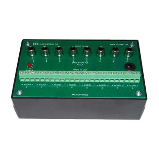
The SMI8 is a 8 channel interface for use with all SM1 series microphones. It provides a convenient way of supplying
power to the SM1, installer friendly termination of the cable runs and standard RCA or 3.5mm audio output connectors.
The SMI8 easily connects to recording equipment such as DVRs, I/P cameras, time-lapse VCRs and audio recorders.
Note the audio output signals of the SMI8 are "line level" (0dbm).
SM1 Microphone Placements
Locate the SM1 microphones as close as possible to the areas of interest in the spaces to be monitored. If large areas are
to be monitored, locate the SM1s in the middle of the rooms. Do not mount the microphones near air conditioning vents,
light fixtures or electrical equipment. The SM1 should be placed at least 5 feet away from the subject(s) to be monitored.
The SM1s are still useable in the range of 15-25 feet but is dependent on the level of background noise in the areas.
Experimentation in the environment will determine what distances work best.
Mounting
The SM1s can be surface or flush mounted on ceilings or walls. For flush mounting, cut a 2 ¼" by 2
" hole in the wall or
¾
ceiling tile to allow room for the circuit board and mount the SM1 to the surface with screws. For surface mounting
applications, Purchase SM1-LEs. Or use a single gang electrical boxes.
SMI8 location and power
The SMI8 interface box is designed to be located next to a DVR or I/P camera. The SMI8 requires a 120VAC power
source within 3 feet of its location. If this is not possible in your application, you can splice in up to 100 feet of 20 awg, 2
conductor cable to extend the distance between the AC power source and the SMI8.
Cable Runs
Run 8 each, 22 gauge, stranded, two conductor shielded cables between the SMI8 interface and the SM1 microphones.
Keep the cable run distances under 1,000 feet and away from AC power sources, light fixtures and electrical equipment.
See Figure 1 for connection diagram.
Adjusting the SM1 Gain
Start with a midrange setting of the gain control on the SM1. Adjust the control + or – for maximum clarity. If the sound at
the amplifier is distorted, rotate the control towards the – mark (counter- clockwise). If the volume at the amplifier is too
low, rotate the control towards the + mark (clockwise).
Setting the SM1 Jumpers
The SM1 microphone has jumper selectable treble boost and limiter circuits. The treble boost circuit when jumpered in,
emphasizes the high frequency sounds that the microphone picks up. This is useful for improving the sound quality on
slow speed tape recordings (VCR time-lapse recordings). The limiter circuit, when jumpered in, automatically reduces the
SM1's output during loud sound intervals. This eliminates the need for the listener to reduce the volume control on the
amplifier when sounds get louder.
Note: It is not recommended to use the SM1's limiter circuit if you are using a tape recorder or other device that already
employs an AGC or limiter circuit. Most tape recorders have limiter circuits. The recommended jumper settings are as
follows:
Stand-alone Application
Tape Recorder Application
Limiter
"IN"
"OUT"
Treble Boost
"OUT"
"IN"
Advertisement
Table of Contents

Subscribe to Our Youtube Channel
Related Manuals for ETS SMI8


Summary of Contents for ETS SMI8
- Page 1 SMI8 location and power The SMI8 interface box is designed to be located next to a DVR or I/P camera. The SMI8 requires a 120VAC power source within 3 feet of its location. If this is not possible in your application, you can splice in up to 100 feet of 20 awg, 2 conductor cable to extend the distance between the AC power source and the SMI8.
- Page 2 Warranty All ETS products carry a one year parts and labor warranty. This warranty does not cover damages as a result of misuse, improper handling of the unit or exposure to extreme temperatures or moisture. At its discretion, ETS reserves the right to repair or replace this unit under the conditions of the warranty.
Need help?
Do you have a question about the SMI8 and is the answer not in the manual?
Questions and answers