
Related Manuals for PEM SprayWand P-500

Summary of Contents for PEM SprayWand P-500
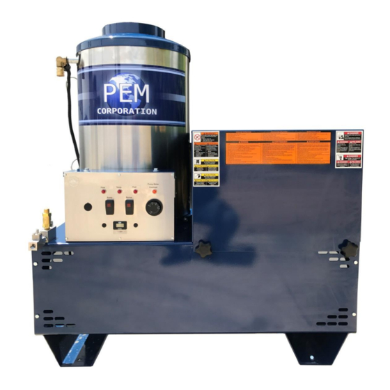
- Page 1 PEM P-500 SprayWand™ Pretreatment Application System Installation • Operation • Maintenance • Troubleshooting Revision 07.02.17...
-
Page 3: Table Of Contents
Table of Contents Introduction ....................3 General specifications ..................3 Limited warranty ....................4 Safety ......................... 6 Safety Rules ....................6 Installation ....................10 Machine delivery and inspection ..............10 Machine identification ..................10 Machine location ..................... 10 Machine setup ....................11 Electrical service .................. - Page 4 Winterizing the machine .................. 23 Preventative maintenance ................24 Pressure hose ....................24 Water inlet tank filter screen ................25 Pump ........................ 25 Pump lubrication..................25 Pump belt ..................... 27 High-pressure filter ..................28 Heating coil descaling ..................29 Machine exterior ....................30 Repair ......................
-
Page 5: Introduction
The heavy-duty system and precision fixed-ration chemical injectors ensure consistent outputs and results. The PEM system features an optional air-activated gel pump. This allows the operator to apply gel products to metal surfaces that standard cleaners cannot handle. -
Page 6: Limited Warranty
Limited warranty PEM Corporation warrants each machine sold by us to be free from manufacturing defects in normal service for 90 days commencing with the delivery of the machine to the original owner. - Page 7 PEM Corporation makes no warranty with the respect to trade accessories. They are subject to the warranties of their manufacturers.
-
Page 8: Safety
Also be review and follow the safety decals on the machine. Note: PEM Corporation encourages the use of environmentally friendly chemicals and waste storage and disposal practices. Always store and/or dispose of chemicals in a manner that complies with local, state and federal regulations. - Page 9 Warning: Operate and maintain the machine in a manner that prevents injury to you and others and damage to equipment. Specifically: Never alter or modify the equipment. Never exceed the factory pressure or temperature rating of the system. Be sure all accessory equipment and system components used will withstand the pressure developed.
- Page 10 Always be certain that the machine safety decals are kept clean and legible. Replace any decals that become damaged, lost or painted over. Always disconnect the electrical plug before performing any repairs or service on machine. Never attempt repairs or modifications that you do not understand. Contact your service dealer or contractor.
- Page 11 Do not use the hose if cuts, leaks, abrasions, bulges or coupling damage is evident. Do not use the hose if any reinforcement is exposed. Do not attempt field repairs through an unauthorized hydraulic hose repair shop. Special couplings and crimping specifications are required for steam and high-pressure washer discharge hose.
-
Page 12: Installation
Installation Machine delivery and inspection Before unpacking, check the machine for any damage that may have occurred during shipment. Note any damage and immediately contact the carrier to make a damage or shortage claim. Machine identification The machine model number, serial number and specifications are stamped on an identification plate that is permanently attached to the right rear side of the machine main frame. -
Page 13: Machine Setup
Danger: Do not locate the machine in a small, enclosed area. Without adequate ventilation, incomplete combustion carbon monoxide and overheating will result. Carbon monoxide can cause death. If the machine must be located out of sight of the operator, special equipment or controls may be required to provide proper operation and ensure operator safety. -
Page 14: Mechanical (Gas) Service
To further ensure machine grounding, a separate external grounding lug has been provided. It is located below the nameplate. In certain areas, it is either recommended or required that a separate ground wire be attached to this lug and to an available ground source, such as a metal water line or ground rod (see Figure 2). -
Page 15: Guide To Gas Line Pipe Size
Butane or propane gas-fired machines: Operate on 11” (3.6 oz.) water column pressure. These propane (LP) gas machines are not equipped with a gas regulator. Therefore, install on the LP tank a gas regulator (see Figure 3) of sufficient size to allow for pressure drop from the tank to the machine. -
Page 16: Venting The Machine To The Outside
Pipe length (feet) Pipe diameter (inches) 10’ ¾” 10’ – 30’ 1” 30’ – 125’ 1 ¼” 125’ – 200’ 1 ½” Table 2: Minimum gas line iron pipe size Venting the machine to the outside Caution: Chimney stacking for the burner venting should be made by a licensed technician and conforms to all federal, state and local codes regarding burner ventilation. -
Page 17: Water Supply
Water supply Connect the machine to a cold water supply tap in the back of the machine (see Figure 6). The water supply must equal to at least 1.5 times the gallon per minute (gpm) output of the machine. If wide variations in water pressure occur, install a pressure regulator in the supply line. -
Page 18: Wand And Hose
Black wand will be used for Rinse ONLY. Do not use the black wands for chemical application. Consult a PEM representative before purchasing additional or replacement wands as the color representation varies. 16 | P a g e... -
Page 19: Initial Start-Up
If the indicator light turns on, turn off the pump switch and let the machine cool down. Turn the pump switch on again. If the pump motor continues to shut down, call PEM. Flow indictor light – This light will glow red during normal operation when the gun trigger is pulled, indicating the circuit through the flow switch is good. -
Page 20: Temperature Control
Temperature control Located to the right of the indicator lights, this knob is turned to set the water temperature (210° F Max). The burner will cycle on and off to maintain the selected water temperature. Caution: Left loose, the gun or wand assembly could damage and cause injury to personal or property damage. -
Page 21: Initial Startup Procedure
Initial startup procedure 1. Inspect connections for any leaks and tighten if necessary. 2. With the nozzle removed from the wand, turn on the Pump switch to start the pump. 3. Run the machine for 1 minute. Operate the trigger once or twice. 4. -
Page 22: Adjusting Chemical Concentration
Continue to hold the trigger until the burner extinguishes, and then turn the Pump switch off. This will prevent damage to the machine. Do not attempt to restart the machine, and contact PEM. Ph: 507-345-1512 Fax: 507-345-5828 email: cs@spraywand.com... - Page 23 Note: When using the optional acidic injection system, the operator can switch from wash mode to rinse mode by closing the siphon valve on the optional injector between freshwater and seal rinse, but the rinse will be 1500 psi and could cause the coating to wash away.
-
Page 24: Daily Operation
Daily Operation Starting the machine 1. Turn on the Burner switch. 2. Turn on the Pump switch. Note: The pump is designed to operate in either direction; rotation direction is not an issue. Caution: To prevent damage to the machine, follow the steps in the Maintenance section. -
Page 25: Winterizing The Machine
Winterizing the machine Caution: Do not store the machine where it will be subject to freezing temperatures, otherwise severe damage will occur. If it must be stored where the temperature is below 32° F/0° C, winterize the machine as follows: 1. -
Page 26: Preventative Maintenance
Preventative maintenance Warning: To prevent damage to the machine and injury of personnel, make daily inspections of the machine for anything that could cause damage, fire or any other safety problem. Warning: To prevent injury from electric shock or accidental machine startups, disconnect the electrical power supply before servicing any part of the machine. -
Page 27: Water Inlet Tank Filter Screen
Water inlet tank filter screen The stainless steel screen located in the float tank (see Figure 7: Float Tank) prevents foreign material from entering the pump. Check the screen frequently to ensure that it does not clog. Caution: To prevent damage, never operate the machine with the filter screen removed. - Page 28 Figure 11: Oil site glass Change the oil after the initial 50 hours of operation and then after every three months or 500 hours of operation, whichever occurs first. Change the oil as follows: 1. Drain the oil by 1) removing the plug located at the rear of the pump crankcase or 2) removing the fill plug (Figure 12) and suctioning the oil out with a suction gun that has a flexible tub.
-
Page 29: Pump Belt
Pump belt New belts will loosen after a short amount of use, and the tension must be readjusted 1. Measure belt defection at the longest span of belt, midway between the pulleys. With a 25-lb vertical force applied, ensure the deflection is no more than 1/2”... -
Page 30: High-Pressure Filter
4. If the filter element is intact, clean it, lightly grease the rubber seat inside the end cap and replace the element. If the element is not intact, obtain a replacement kit (element, spring, white ring) from PEM, and replace it. -
Page 31: Heating Coil Descaling
Heating coil descaling With any heating coil, water deposits can settle on the inner wall of the steel pipe, causing several problems. These scale deposits act as an insulator, limiting water temperature rise and causing hot spots where the coil starts to deteriorate. -
Page 32: Machine Exterior
4. Put the end of the free hose to a drain. Watch the hose discharge. When the water is completed (i.e., when there is 10 seconds of air in the line), turn the descaler off, and place the hose into the descaling compound. -
Page 33: Repair
Repair Pump Servicing the pumping section The three inlet and three discharge valves are identical and can be serviced without disrupting the inlet or discharge piping using a valve kit available from the manufacturer. Two kits will be needed to repair all the valves in the pump. The kit includes new O-rings and a valve assemblies (valve seat, poppet, spring and retainer all preassembled). -
Page 34: Servicing The Ceramic Plungers And V-Packings
Figure 18: Removing the valve assemblies 4. Remove the O-ring from the cavity. 5. Install the new O-ring in the valve cavity. 6. Insert the new valve assembly into the valve cavity. 7. Replace the valve cap and torque it to 70-75 foot-pounds. Servicing the ceramic plungers and V-packings Removing the pump manifold head 1. -
Page 35: Replacing Plungers
Figure 20: Removing the manifold head Caution: When sliding the head from the crankcase, be careful not to damage the plungers. 3. The V-packing assemblies may come off with the head. If not, slide them off and examine the ceramic plungers. Their surface should be smooth and not scored or pitted. -
Page 36: Replacing V-Packings
6. Slide the new plunger over the piston rod, and torque it to 5 foot- pounds. Replacing V-packings 1. From the crankcase side of the manifold head, use a reverse pliers to remove the low pressure seal from the seal case. 2. - Page 37 Figure 23: Pump exploded view 35 | P a g e...
-
Page 38: Pump Parts List (5Cp310, 5Cp3120G1, 5Cp3130G1)
Pump parts list (5CP310, 5CP3120G1, 5CP3130G1) Item Part number Material Description Quantity 30057 Key (M6x6x25) 96031 STZP Screw, Sems (M8x16) 46910 Cover, Bearing O-ring, Bearing 14028 Cover -70D 43222 Seal, Oil, Crankshaft 14480 Bearing, Ball †48658 Rod, Connecting Assembly [2/00] 46928 Crankshaft, Duel End –... - Page 39 Screw, Sems 92519 STZP (M6x16) 25625 STCP Plug, Draign (1/4” x 19BSP) O-Ring, Drain Plug – 23170 46940 Cover, Rear 14044 O-Ring, Rear Cover 48617 Crankcase 46746 Pin, Crosshead 48458 BBNP Rod, Plunger 46838 Seal, Oil, Crankcase – 43900 Slinger, Barrier 45697 Washer, Keyhole (M18)
- Page 40 O-Ring, Seal Case – 13978 14329 O-Ring, Seal Case Seal, HPS w/s Seal, HPS w/SS 43319 PTFE V-Packing 46287 V-Packing V-Packing 46618 Adapter, Male 22179 BBCP Plug, Inlet (1/2” NPT) Back-up-Ring, Seat 17457 O-Ring, Seat 11685 O-Ring, Seat 46658 Seat 46429 Valve 43750...
- Page 41 87872 STZP Screw, HSH (M8x70) Plug, Discharge (3/8” 22187 BBCP NPT) 118672 STCP Protector, Shaft 39 | P a g e...
-
Page 42: Intermittent Ignition Device
Intermittent ignition device Note: This unit is not field repairable. Attempted repair for tampering the unit will void warranties. Wiring The control module requires a power source of 24 volts, 60 Hz. Use UL style 1015 for all thermostat, pilot valve, main valve and ground wire connections to the control module. -
Page 43: Engineering Data
Figure 25: Intermittent ignition device front with chart of fail codes. Engineering data Note: Specifications subject to change without notice Ignition means: Intermittent Flame-establishing period: Continuous pilot burner Flame failure response time: Main gas shut off: 2.0 seconds (max) Pilot gas: Continuous Flame failure re-ignition time: 0.8 seconds max Voltage: 24 Vac, 60 Hz Note: Total current drain for control will include gas valve loads in addition to... -
Page 44: Gas Valve
Maximum HV lead length: 54” Maximum operating temperature: HV lead: 250° C Wiring Harness (except sensor lead): 105° C Relay contact load: 2 Amp. Inductive and 24 Vac, 60 Hz Main valve control: Controlled by relay contact through the main valve terminals. -
Page 45: Adjusting The Pilot Light
Figure 26: Gas Valve exploded diagram Adjusting the pilot light 1. Remove the adjusting cap using a fine screwdriver. 2. The pilot flame should be about 2-inches high. Turn the pilot adjustment cap (screw) clockwise to make the pilot lower. Turn the pilot adjustment cap counterclockwise to make the pilot higher. -
Page 46: Troubleshooting
Troubleshooting Warning: To prevent serious or fatal injury, ensure the machine is shutoff and disconnected from the electrical supply before attempting any repairs or maintenance. Use lockout-tagout procedures. Troubleshooting is an organized study of the problem and a planted method of investigation and correction. -
Page 47: Gas Burner Malfunction
Gas burner malfunction Problem Probable cause Solution Pilot will not light Gas cock dial turned off 1. Turn dial on. (temperature light does Gas leak 2. Check fittings with soapy water, and tighten any loose fittings not turn on). Low or High gas pressure 3. -
Page 48: Intermittent Ignition Device Problems
Limed up heating coil. Descale the unit. Burner control circuit faulty Check the circuit for loose wiring. Reestablish power. keeping gas valve closed. Increase water temperature. Low temperature tap water Excessive temperature Temperature set too high Decrease thermostat setting. output Faulty thermostat Replace thermostat. - Page 49 Inadequate water supply to Check for restricted inlet and adequate tap water supply. the pump, creating a Check key and tighten set screw. Noisy operation, “vacuum knock” Replace bearing(s). knocking Loose pulley Replace pump. Worn or broken bearing(s) Faulty pump shaft Oil leaks Worn crank seals, crankcase cover Replace seals.
-
Page 50: General Malfunctions
General malfunctions Problem Probable cause Solution Machine cycles (4 Chemical injector clogged 1. Replace the chemical injector. seconds) Nozzle clogged 2. Disassemble the nozzle and clean the elements. Filter clogged Air leak 3. Clean or replace the filter (see the maintenance section). 4. -
Page 51: Electrical Malfunction
Electrical malfunction Problem Probable cause Solution Washer electrically No power to machine Check the circuit breaker. Check for a defective electrical outlet. dead Defective Pump switch Test the switch, and replace if it is defective. Faulty or loose wiring Contact qualified service technician. Power supply circuit Short circuit in the washer Check washer (and other loads on the same circuit) for faulty or loose... - Page 52 Figure 27: Electrical diagram 50 | P a g e...
-
Page 53: Service Record
Service record Type Date _________________________________________ _________ _________________________________________ _________ _________________________________________ _________ _________________________________________ _________ _________________________________________ _________ _________________________________________ _________ _________________________________________ _________ _________________________________________ _________ _________________________________________ _________ _________________________________________ _________ _________________________________________ _________ _________________________________________ _________ _________________________________________ _________ _________________________________________ _________ _________________________________________ _________ _________________________________________ _________ _________________________________________ _________ _________________________________________ _________ _________________________________________ _________ 51 | P a g e... - Page 54 320 Mallard Lane Mankato, MN 56001 USA T: 507-345-1512 F: 507-345-5828 www.spraywand.com Parts and Service: T: 888-969-1601 Email: sales@spraywand.com...
Need help?
Do you have a question about the SprayWand P-500 and is the answer not in the manual?
Questions and answers