
Summary of Contents for Benevo BPGH4L
- Page 1 BPGH4L 4K UHD HDMI Signal Generator & Analyzer (Portable Version) Operation Manual Operation Manual...
- Page 3 BENEVO Technology assumes no responsibility for any inaccuracies that may be contained in this document. BENEVO also makes no commitment to update or to keep current the information contained in this document.
- Page 4 SAFETY PRECAUTIONS Please read all instructions before attempting to unpack, install or operate this equipment and before connecting the power supply. Please keep the following in mind as you unpack and install this equipment: • electrical shock and injury to persons. •...
-
Page 5: Table Of Contents
CONTENTS 1. Introduction ............1 2. Applications .............1 3. Package Contents ..........1 4. System Requirements ........2 5. Features ............2 6. Operation Controls and Functions ....3 6.1 Front Panel ..........3 6.2 Top Panel ........... 5 6.3 Battery Compartment ......6 6.4 OLED Display ..........7 6.5 OSD Menu .......... -
Page 6: Introduction
1. INTRODUCTION This portable HDMI Signal Generator & Analyzer provides a convenient way to test and verify all aspects of an HDMI signal path, including source and sink. This unit complies with the HDMI 2.0a and HDCP 1.4/2.2 standards. The unit’s Analyzer mode complies with the CEA standard HDR static metadata extensions CEA-861-F and CEA-861.3 for EDID analysis. -
Page 7: System Requirements
4. SYSTEM REQUIREMENTS HDMI receiving equipment such as an HDTV, monitor or audio video game console or set-top box. 5. FEATURES • HDMI input and output with 18Gbps (600MHz) 4K UHD support • DVI 1.0 compliant with the use of an HDMI-DVI adaptor •... -
Page 8: Operation Controls And Functions
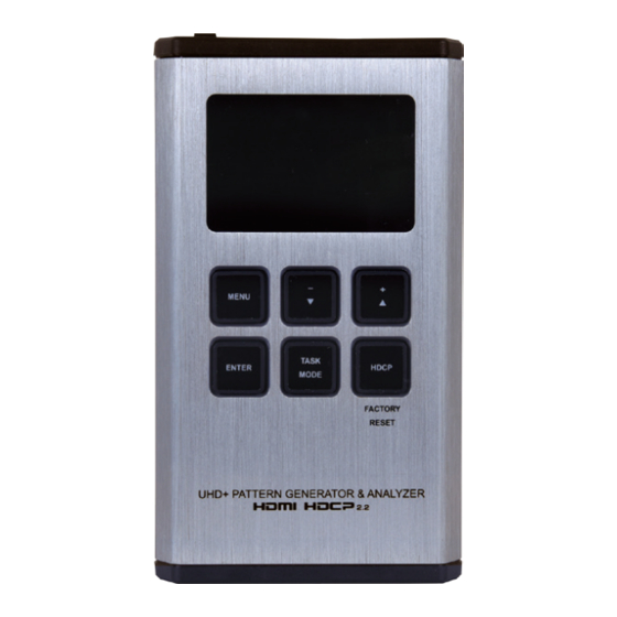
• • Portable palm-sized design with easy to use front-panel controls 6. OPERATION CONTROLS AND FUNCTIONS 6.1 Front Panel MENU TASK ENTER HDCP MODE FACTORY RESET UHD+ PATTERN GENERATOR & ANALYZER OLED: This screen’s layout changes depending on the unit’s operational mode and selected function. - Page 9 Analyzer Mode: The status line will display the 5V, TMDS clock, and sync detection state of the connected source. (1 = detected, 0 = not detected.) Analyser 5V. 0 Clk. 0 Syn. 0 Main Menu Input Setup Monitor Source Monitor HDCP Monitor SCDC Pattern Mode: The status line will display the RxSense and Hot-plug...
-
Page 10: Top Panel
ENTER: item. Note: In Analyzer and Pattern modes, press and hold this button for 2 seconds to turn audio On or Off. TASK MODE: Press to switch the unit between Analyzer Mode, Pattern Mode, and Cable Test Mode. Note: In Analyzer mode, press and hold this button for 2 seconds to toggle the input’s hot plug trigger. -
Page 11: Battery Compartment
6.3 Battery Compartment While this unit may be powered directly via the USB port, it is more typically powered by a rechargeable Lithium-ion battery (not included) which is concealed within the bottom of the unit. Opening the Compartment: behind the base panel and the bottom cover will pop out. -
Page 12: Oled Display
6.4 OLED Display • Power Saving Mode The OLED display will automatically switch off after the set number of minutes. All other functions of the unit will continue normally while indicate it is in power saving mode. To turn the OLED display back on, press any key. -
Page 13: Osd Menu
6.5 OSD Menu 6.5.1 Analyzer Mode ANALYZER MODE LEVEL 1 LEVEL 2 LEVEL 3 50ms ~ 500ms (150ms) Input Setup Hotplug Time Hotplug Toggle *PoR RxSense *PoR DDC Bus *PoR HDCP Port v1.4 v1.4+v2.2 HDCP REAUTH-REQ 4K to 1080p On YCbCr Out On RGB Out *PoR SCDC Port... - Page 14 ANALYZER MODE LEVEL 1 LEVEL 2 LEVEL 3 Monitor HDCP (v1.4) Aksv [Analytic Data] Bksv Ri Source Ri’ Rx Count Day 0 00 : 00 : 00 Monitor HDCP (v2.2) Source HDCP [Analytic Data] Rx HDCP Port TxCaps RxCaps Receiver ID Monitor SCDC Rx SCDC Port [Analytic Data]...
- Page 15 ANALYZER MODE LEVEL 1 LEVEL 2 LEVEL 3 Video Timing Data Rate [Analytic Data] Bit Depth, 3D, Y4:2:0, Scramble Total (H/V Total Pixel/Line) (H/V Active Pixel/Line) Polarity (H/V Sync. Polarity) Scan HFreq (H Sync. Frequency) VFreq (V Sync. Frequency) Offset1 (H/V Sync.
- Page 16 ANALYZER MODE LEVEL 1 LEVEL 2 LEVEL 3 Packet GCP 0x03 [Analytic Data] AVI 0x82 AIF 0x84 SPD 0x83 VSIF H14b 0x81 DRMI (HDR) 0x87 EDID Analyzer Sink [Analytic Data] Rx EDID [D1] DVI [Default EDID Details] [D2] VGA [D3] 8B LPCM PC [D4] 8B LPCM HD [D5] 12 BS 720p [D6] 12 BS HD 3D...
- Page 17 ANALYZER MODE LEVEL 1 LEVEL 2 LEVEL 3 EDID Emulator [D10] 12 HBR 4K6G [Default EDID Details] [C1 ~ 10] Copy 01 ~ 10 [Copied EDID Details] EDID Copy Sink [C1 ~ 10] Copy 01 ~ 10 [Copied EDID Details] EDID Burn Sink [D1] DVI [Default EDID Details]...
-
Page 18: Pattern Mode
6.5.2 Pattern Mode PATTERN MODE LEVEL 1 LEVEL 2 LEVEL 3 Output Setup Timing [T1] 720×480p59 [T2] 720×576p50 [T3] 1280×720p25 [T4] 1280×720p30 [T5] 1280×720p50 [T6] 1280×720p60 [T7] 1920×1080i50 [T8] 1920×1080i60 [T9] 1920×1080p24 [T10] 1920×1080p25 [T11] 1920×1080p30 [T12] 1920×1080p50 [T13] 1920×1080p60 [T14] 3840×2160p24 [T15] 3840×2160p25 [T16] 3840×2160p30... - Page 19 PATTERN MODE LEVEL 1 LEVEL 2 LEVEL 3 Output Setup Pattern [P6] Red [P7] White [P8] Yellow [P9] Color Bar [P10] Grayscale 256 [P11] V Line OnOff HDMI Format Colorspace YUV444 Full ColorRange Limited *PoR Audio LPCM 5.1CH 7.1CH HDCP Out v1.4 v2.2 HDCP V2.2 AKE_Stored_...
- Page 20 PATTERN MODE LEVEL 1 LEVEL 2 LEVEL 3 Monitor HDCP Tx HDCP [Analytic Data] (Output HDCP 1.4) Sink HDCP Port Aksv Bksv Ri Tx Ri’ Sink Count Day 0 00:00:00 Monitor HDCP Tx HDCP [Analytic Data] (Output HDCP 2.2) Sink HDCP Port TxCaps RxCaps Receiver ID...
- Page 21 PATTERN MODE LEVEL 1 LEVEL 2 LEVEL 3 Monitor SCDC ENTER Reset/Start [Analytic Data] HF VSDB SCDC Exist 0 ~ 80 (70) Audio Output Volume 48 kHz Sample Rate 96 kHz 192 kHz Word Length 16 Bits 20 Bits 24 Bits *PoR Channels SD0-L ~ SD03-L Freq.
- Page 22 PATTERN MODE LEVEL 1 LEVEL 2 LEVEL 3 HDR Emulator AVI Colorimetry xvYCC709 sYCC601 Adobe Y601 Adobe RGB EOTF [0] SDR Lumi Range [1] HDR Lumi Range [2] SMPTE ST2084.2 [3] Future EOTF S. Metadata Type 1 Metadata Descr. Reserved 0 ~ 65500 (0) Max.
-
Page 23: Cable Test Mode
6.5.3 Cable Test Mode CABLE TEST MODE LEVEL 1 LEVEL 2 LEVEL 3 Run Test [Analytic Data] (Enter–Start/Stop) (PASS or FAIL result) Hotplug DDC Bus 4K6G A/V Normal Cable Setup Level Strict Length 2 minute Time 5 minute 10 minute 15 minute 30 minute 1 hour... - Page 24 Factory Default Items in Bold are the factory default settings. Run Test FAIL result shows on the 2nd page. Please press the down button to view this information. Cable Testing The cable testing feature performs tests based on the HDMI provided as an advisory tool only.
-
Page 25: Test Timings
6.5.4 Test Timings 1. Output Resolutions (Pattern Mode) This unit supports a total of 23 output resolution timings when in Pattern Mode. Test Timing List 720×480p 720×576p 1280×720p 1920×1080i 1920×1080p 3840×2160p 4096×2160p... - Page 26 2. Input/Output Resolutions (Analyzer Mode) This unit provides 3 options for how to handle the output of 4K video input sources when in Analyzer mode. These choices are selectable from the “Input Setup” menu using the “4K to 1080p” item. •...
- Page 27 Input Output Vertical PC Resolution Frequency (Hz) HDMI HDMI 1600×900p 60 (RB) 1600×1200p 1680×1050p 60 (RB), 60 1920×1200p 60 (RB) Note: RB = Reduced Blanking. Input Output Vertical PC Resolution Frequency (Hz) HDMI HDMI 480i...
-
Page 28: Test Patterns
6.5.5 Test Patterns 1. Output Video Support (Pattern Mode) There are a total of 11 test patterns available for output when in Pattern Mode. Test Pattern Name Variations Black Blue Cyan Green Magenta White Yellow Color Bar Grayscale 256 Line On/Off-V 1. - Page 29 9. Color Bar The Color Bar pattern is a series of repeating vertical colored bars (white, yellow, cyan, green, magenta, red, blue, black). This pattern is not available when the output color range is set to "Limited". 10. Grayscale 256 Gray The Grayscale 256 brightness and grayscale tracking of your display with a full 265 step...
- Page 30 When outputting 4K@50/60Hz the pattern will consist of double, rather than single, pixel lines. This pattern is not available when the color space is set to YUV 4:4:4, or the color range is set to "Limited". 2. Output Audio Support (Pattern Mode) Audio Sampling Word...
-
Page 31: Rs-232 Protocol
6.6 RS-232 Protocol When the unit is set to RS-232 mode in the System menu and connected to a PC via a USB cable, the following COM port settings should be used for direct control. SERIAL PORT SETTINGS Baud Rate 115200 Data Bits Parity Bits... - Page 32 COMMANDS DESCRIPTION VARIABLES $? Show full command list. $HELP Show full command list. $4K_TO_1080P N1 Available values for N1: Set the 4K downscaling mode. [No downscaling] ON_RGB [1080p, RGB color] ON_YUV [1080p, YUV color] $4K_TO_1080P? Display the current 4K downscaling mode. $AUDIO_CH N1...
- Page 33 COMMANDS DESCRIPTION VARIABLES Available Values for N1: Display the internal audio output frequency of the selected SD0_L [SD0 Left Channel] channel (in Hz). SD0_R [SD0 Right Channel] SD1_L [SD1 Left Channel] SD1_R [SD1 Right Channel] SD2_L [SD2 Left Channel] SD2_R [SD2 Right Channel] SD3_L [SD3 Left Channel]...
- Page 34 COMMANDS DESCRIPTION VARIABLES $CABLE_LEVEL N1 N1 = NORMAL, STRICT Set the cable test level. $CABLE_LEVEL? Display the cable test level. $CABLE_RESULT? Display the cable test result. $CABLE_RUN N1 N1 = START, STOP Start or stop the cable testing process. $CABLE_RUN? Display the cable test status.
- Page 35 COMMANDS DESCRIPTION VARIABLES $EDID_COPY_SINK N1 N1 = C1 ~ C10 Copy the current HDMI sink’s EDID to the designated copy slot. If the copy fails “$err” will be displayed. $EDID_MANUF? N1 Available values for N1: Display the manufacturer name stored in the EDID of the selected [HDMI Input (Rx) Port] location.
- Page 36 COMMANDS DESCRIPTION VARIABLES $EDID_READ N1,N2 Available values for N1: Displays the selected data block stored in the EDID of the selected D1 ~ D10 [Default EDID 1 ~ 10] location. C1 ~ C10 [Copy EDID 1 ~ 10] SINK_H [HDMI Sink] Available values for N2: BLOCK0 [EDID Block 0]...
- Page 37 COMMANDS DESCRIPTION VARIABLES $EDID_WRITE N1,N2 N3 Available values for N1: Directly write an EDID block to the selected EDID location. [HDMI Input(Rx) Port] SINK_H [HDMI Sink] Available values for N2: BLOCK0 [EDID Block 0] BLOCK1 [EDID Block 1] N3 = <CR><LF>{128 byte hex data} The data must be sent as a 128 byte hex data bit stream following the <CR><LF>...
- Page 38 COMMANDS DESCRIPTION VARIABLES $HDCP_IN_VER N1 Available values for N1: Set the HDCP version to use on the unit’s HDMI input. V1.4 [HDCP v1.4 only] V1.4+V2.2 [HDCP v1.4 & v2.2] Affects Analyzer mode only. $HDCP_IN_VER? Display the current HDCP version used on the unit’s HDMI input. $HDCP_OUT_SW N1...
- Page 39 COMMANDS DESCRIPTION VARIABLES $HDR_EOTF N1 Available values for N1: Set the HDR EOTF (Electro-Optical Transfer Function) mode. [Traditional Gamma, SDR Luminance Range] [Traditional Gamma, HDR Luminance Range] 2084 [SMPTE ST 2084] RSVD [Reserved for future use] $HDR_EOTF? Display the current HDR EOTF mode.
- Page 40 COMMANDS DESCRIPTION VARIABLES $HDR_TX_COL N1 Available values for N1: Set the HDMI output (Tx) AVI Colorimetry mode. [No Data] [ITU 601] [ITU 709] [xvYCC 601] [xvYCC 709] [sYCC 601] [Adobe Y601] [Adobe RGB] [BT.2020 (1) Y' [BT.2020 (2) R'G'B'/Y'C' $HDR_TX_COL? Display the current HDMI output (Tx) AVI Colorimetry mode.
- Page 41 COMMANDS DESCRIPTION VARIABLES $RX_DDC N1 N1 = ON, OFF Enable or disable the DDC bus for the HDMI input (Rx). $RX_DDC? Display the DDC bus state for the HDMI input (Rx). $RX_HOTPLUG N1 Available values for N1: Set the hot plug value for the HDMI input (Rx).
- Page 42 COMMANDS DESCRIPTION VARIABLES $RX_SCDC? Display the current SCDC port state for the HDMI input (Rx). $RX_SENSE N1 N1 = ON, OFF Enable or disable the RxSense function for the HDMI input (Rx). $RX_SENSE? Display the current RxSense state for the HDMI input (Rx). $SINK_DETECT? N1...
- Page 43 COMMANDS DESCRIPTION VARIABLES SCDC_SOURCE_VER [SCDC source version] CKDT [TMDS clock detection] DATA_RATE [Video data rate in Mbps] TMDS_FORMAT [Detected TMDS format (DVI/HDMI)] SCDT [TMDS sync detection] [Horizontal active pixels] [Horizontal back porch pixels] [Horizontal front porch pixels] [Horizontal sync width pixels] [Total horizontal pixels] [Horizontal sync polarity] HVS_OFFSET1...
- Page 44 COMMANDS DESCRIPTION VARIABLES [Display packet-AVI data] DRMI [Display packet-DMI data] [Display packet-GCP data] [Display packet-SPD data] [Display packet-VSI data] SCDC_SCR_ENABLE [Rx SCDC source enable scrambling state] SCDC_SCR_STATUS [SCDC sink scrambling status] SCDC_SINK_VER [SCDC sink version] SCDC_SOURCE_VER [SCDC source version] $TASK_MODE N1 Available values for N1: Set the unit’s operation mode to Signal Analyzer or Pattern...
- Page 45 COMMANDS DESCRIPTION VARIABLES $TIMING N1 Available values for N1: Select the output resolution timing to use. [720×480p@59] [720×576p@50] [1280×720p@25] [1280×720p@30] [1280×720p@50] [1280×720p@60] [1920×1080i@50] [1920×1080i@60] [1920×1080p@24] [1920×1080p@25] [1920×1080p@30] [1920×1080p@50] [1920×1080p@60] [3840×2160p@24] [3840×2160p@25] [3840×2160p@30] [3840×2160p@50] [3840×2160p@60] [4096×2160p@24] [4096×2160p@25] [4096×2160p@30] [4096×2160p@50] [4096×2160p@60] $TIMING? Display the unit’s current output resolution timing by timing number.
- Page 46 COMMANDS DESCRIPTION VARIABLES $TMDS_FORMAT? Display the current video output format. $TMDS_SW N1 N1 = ON, OFF Enable or disable video output. [Off disables video output] $TMDS_SW? Display the current video output status. $TX_5V N1 Available values for N1: Set the unit’s output +5V pin state to follow the TMDS output state or FOLLOW [Only output 5V if...
-
Page 47: Connection Diagram
7. CONNECTION DIAGRAM UHDTV HDMI Source Device HDMI HDMI Output Input PC/Laptop MENU TASK ENTER HDCP MODE FACTORY RESET UHD+ PATTERN GENERATOR & ANALYZER... - Page 48 8. SPECIFICATIONS Video Bandwidth 600MHz/18Gbps Input Port 1×HDMI Output Port 1×HDMI Control Interface 1×USB Micro-B HDMI Cable Length 10m (1080p@60Hz, 12-bit) 5m (4K@60Hz, 4:4:4, 8-bit) Power Supply 5V/2.1A USB power or Lithium-ion battery (not included) ESD Protection Human Body Model: ±12kV (Air Discharge) ±8kV (Contact Discharge) Dimensions...
-
Page 49: Operational Notes
8.2 Operational Notes • Battery - When the USB port is set to RS-232 mode some power is also provided to the unit via USB, however a properly charged battery is still required to fully operate the unit. - Many USB hubs do not provide proper 5V power to connected devices. -
Page 50: Acronyms
9. ACRONYMS ACRONYM COMPLETE TERM Three-Dimensional Consumer Electronics Control Character Error Detection Display Data Channel Digital Visual Interface EDID EOTF Electro-Optical Transfer Function HDCP High-bandwidth Digital Content Protection HDMI High Dynamic Range HDTV Hertz kilohertz Light-Emitting Diode LPCM Linear Pulse-Code Modulation milliampere hour minute millisecond... - Page 51 ACRONYM COMPLETE TERM TMDS Transition-Minimized Differential Signaling Ultra-High-Definition UHDTV Ultra-High-Definition Television Universal Serial Bus Video Graphics Array...
- Page 52 BENEVO TECHNOLOGY CO., LTD. www.benevo.com.tw...