Advertisement
This is a safety alert symbol and should never be ignored. When you see this symbol on labels or in manuals, be alert to
the potential for personal injury or death.
Improper installation, adjustment, alteration, service
or maintenance can cause property damage, personal
injury or loss of life. Installation and service must be
performed by a licensed professional installer (or
equivalent), service agency or the gas supplier.
Do not store combustible materials near the furnace or
warm air ducts. The material may ignite by spontaneous
combustion creating a fire hazard.
These units are not approved for mobile home
applications. Such use could result in property damage,
personal injury, or death.
If these instructions are not followed exactly, a fire
or explosion may result causing property damage,
personal injury, or loss of life.
Manufactured By
Allied Air Enterprises LLC
A Lennox International, Inc. Company
215 Metropolitan Drive
West Columbia, SC 29170
Check that equipment complies with all applicable building codes, laws, and regulations for its intended use prior to installation.
507388-03
INSTALLATION INSTRUCTIONS
HWC8 V-Series
This manual must be left with the homeowner for future reference.
WARNING
WARNING
WARNING
CAUTION
Models
TM
Table of Contents
Unit Dimensions ..........................................................2
Installation ...................................................................3
Electrical Connections .................................................7
Start-Up .....................................................................11
Operation ...................................................................12
Maintenance ..............................................................14
Wiring Diagrams ........................................................17
For your safety, do not store or use gasoline or other
flammable vapors and liquids in the vicinity of this or any
other appliance. Such actions could result in property
damage, personal injury, or death.
Installation shall be made in accordance with the
requirements of the local utility and other authorities
having jurisdiction, or with the National Fuel Gas
Code, ANSI Z223.1 (latest edition) and the National
Electrical Code. Any alteration of internal wiring will void
certification and warranties.
*P507388-03*
Issue 2110
WARNING
CAUTION
(P) 507388-03
Page 1 of 19
Advertisement

Subscribe to Our Youtube Channel
Related Manuals for magicpak HWC8 V Series

Summary of Contents for magicpak HWC8 V Series
-
Page 1: Table Of Contents
INSTALLATION INSTRUCTIONS HWC8 V-Series Models This manual must be left with the homeowner for future reference. This is a safety alert symbol and should never be ignored. When you see this symbol on labels or in manuals, be alert to the potential for personal injury or death. -
Page 2: Unit Dimensions
Unit Dimensions Line Voltage Voltage Supply 1-3/4 1/2 Gas Inlet 1-1/2 2-3/4 13-3/8 Supply Supply Condensate Drain 18-1/4 (HWC9 Only) 43-3/16 Return Return 2-7/8 29-7/16 27-7/8 Page 2 of 19 Issue 2110 507388-03... -
Page 3: Installation
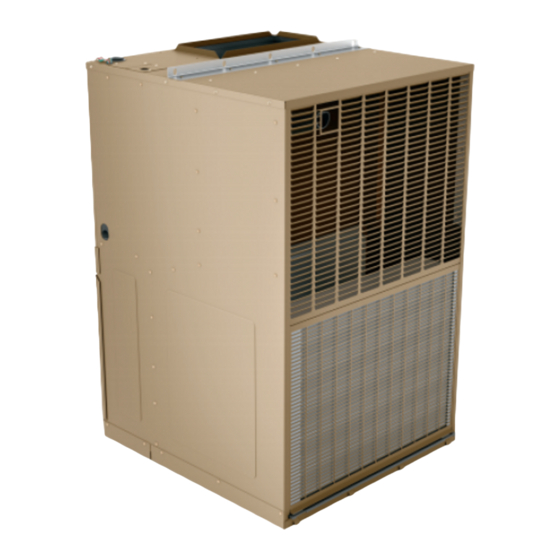
2” from the face of the building and a conspicuous place. should not be obstructed with trees, landscape materials, The MagicPak All-In-One™ HVAC system model HWC8 or building structure. V-Series™ units are self-contained, gas-fired heating There is no minimum clearance required on locating the with electric cooling models. - Page 4 • Return air temperature range between 60°F (16°C) The drain line should pitch gradually downward at least 1” and 80°F (27°C) must be maintained. per 10’ of horizontal run to the open drain trap. • Air filters must be installed in the system and must be Be certain that the plastic drain tube has free drainage and maintained during construction.
- Page 5 1. Seal any unused openings in the common venting system. WARNING Visually inspect the venting system for proper size and Insufficient combustion air can cause headaches, horizontal pitch and determine there is no blockage nausea, dizziness or asphyxiation. It will also cause or restriction, leakage, corrosion, or other deficiencies excess water in the heat exchanger resulting in rusting which could cause an unsafe condition.
- Page 6 CAUTION If a flexible gas connector is required or allowed by the authority that has jurisdiction, black iron pipe shall be installed at the gas valve and extend outside the furnace cabinet. The flexible connector can then be added between the black iron pipe and the gas supply line.
-
Page 7: Electrical Connections
Electrical Connections Exterior Junction Box and Switch All wiring must be done in accordance with the National Electrical Code, ANSI/NFPA No. 70 (latest edition); or local If local codes allow, a field supplied junction box and codes, where they prevail. Any alteration of internal wiring optional switch may be installed on the top panel to provide will void certification and warranty. - Page 8 Thermostat Junction Box Install the thermostat according to the directions furnished Use Screws to secure with it. The thermostat must be located on an inside wall Junction box where it will not be affected by drafts, sunlight, or any other heat producing appliances.
- Page 9 Adjustments – Heating Section Blower The unit contains a direct-drive, multispeed blower. The Temperature Rise proper speeds have been preset at the factory for heating At time of installation, the temperature rise must be and cooling. Refer to the wiring diagram or Table 2 for adjusted to be within the range specified on the unit rating recommended heating/cooling speeds for specific models.
- Page 10 0.1“ w.c. 0.2“ w.c. 0.3“ w.c. 0.4“ w.c. Rise Indoor Blower Unit Voltage Temp Temp Temp Temp Model Range Rise Speed SCFM Rise SCFM Rise SCFM Rise SCFM Rise (°F) (°F) (°F) (°F) (°F) (°F) TAP 1 (HEAT) * 208 or 230 TAP 2 (HEAT) 208 or 230 TAP 3 (HEAT)
-
Page 11: Start-Up
0.1“ w.c. 0.2“ w.c. 0.3“ w.c. 0.4“ w.c. Rise Indoor Blower Unit Voltage Temp Temp Temp Temp Model Range Rise Speed SCFM Rise SCFM Rise SCFM Rise SCFM Rise (°F) (°F) (°F) (°F) (°F) (°F) TAP 1 (HEAT) * 208 or 230 TAP 2 (HEAT) 208 or 230 TAP 3 (COOL) †... -
Page 12: Operation
Operation Blower Control Operation of the unit is automatic and will provide heating and cooling depending on the setting of the thermostat. The blower will start approximately 30 seconds after the burners ignite and will stop approximately 120 seconds after the thermostat is satisfied. The time delay is preset at Heating the factory and timing can not be adjusted. - Page 13 Combustion Flue Collector Box Inducer Remove these screws to remove Combustion inducer Gas Valve Primary Limit (Mounted to Vest panel) Loosen these screws to remove control board mounting bracket Inducer prover switch Gas Manifold ...
-
Page 14: Maintenance
Step 7 Mounting Brackets Burner & Manifold Assembly Step 8 Step 9 Step 10 Figure 9. Burner & Manifold Assembly Removal Maintenance Refer to Figure 8 for heating compartment component layout. WARNING It is recommended that the furnace be inspected annually ELECTRICAL SHOCK, FIRE OR EXPLOSION by a qualified service person. - Page 15 Rollout Switch Disconnect the red and blue wires at the gas valve. If for any reason the heat exchanger becomes blocked Refer to Figure 9. Remove the two screws on the the temperature-sensitive rollout switch located beside the burner assembly that secure it to the mounting burners will open and the ignition control will turn off the brackets.
- Page 16 Burner Orifices Brush out the inside of the flue collector box. Orifices are threaded into the gas manifold. To remove Brush out the inside of the flue tube extension. them: If soot buildup is excessive, clean the combustion 1. Remove the burner & manifold assembly as described inducer wheel and housing.
-
Page 17: Wiring Diagrams
Wiring Diagrams Figure 10. Wiring Diagram - HWC*12,18 507388-03 Issue 2110 Page 17 of 19... - Page 18 Figure 11. Wiring Diagram - HWC*24 Page 18 of 19 Issue 2110 507388-03...
- Page 19 Figure 12. Wiring Diagram - HWC*30 507388-03 Issue 2110 Page 19 of 19...
Need help?
Do you have a question about the HWC8 V Series and is the answer not in the manual?
Questions and answers