Subscribe to Our Youtube Channel
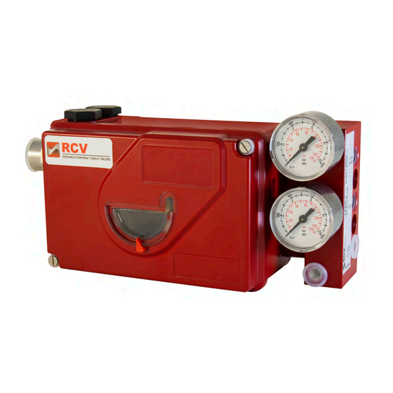
Summary of Contents for Badger Meter RCV SRI990
- Page 1 Valve Positioners SRI990 Analog Positioner Quick Start Guide POS-QS-00007-EN-02 (May 2018)
- Page 2 Valve Positioners, SRI990 Analog Positioner Page ii POS-QS-00007-EN-02 July 2013...
-
Page 3: Table Of Contents
Quick Start Guide CONTENTS Mounting to actuators Mounting to Linear Actuators Mounting to Rotary Actuators Pneumatic Connections Electrical connections START UP (setting by means of local switches and potentiometers) Initial Setting Configuration Direction of Rotation of Feedback Shaft Setting of Zero, Span and Gain Setting and Start Up of position transmitter 4-20mA Adjusting the Start of the Measuring Range (4mA) Adjusting the End of the Measuring Range (20mA) - Page 4 Valve Positioners, SRI990 Analog Positioner Page iv POS-QS-00007-EN-02 July 2013...
-
Page 5: Mounting To Actuators
Mounting to actuators Use this document as a guide for quick startup For more detailed information, see the positioner’s User Manual and Product Data Sheet, available on our website at www.badgermeter.com MOUNTING TO ACTUATORS During operation the flat side of the spindle 9 on the back of the positioner must always point towards the arrow 26 The working angle around this position is ±... -
Page 6: Mounting To Rotary Actuators
Mounting to actuators Feedback Lever for Linear Actuators The carrier bolt B is in the slot of the feedback lever A and the compensating spring F touches the carrier bolt Carrier bolt B: 1 threaded sleeve 2 Stud 3 coupling piece Figure 3: Feedback lever and carrier bolt Mounting to Rotary Actuators Do not tighten grub screw 4 against the thread of spindle 9... - Page 7 Mounting to actuators Actuator, left turning Actuator, right turning Figure 4: Actuators July 2013 POS-QS-00007-EN-02 Page 7...
-
Page 8: Pneumatic Connections
Pneumatic Connections PNEUMATIC CONNECTIONS Air supply: 1 4…6 bar (but not more than the maximum pressure of the actuator), free of oil, dust and water Single acting, direct mounting Single acting Double acting s air supply y1, y2 pneumatic outputs (--) closed Figure 5: Pneumatic connections ELECTRICAL CONNECTIONS... -
Page 9: Startup (Setting By Means Of Local Switches And Potentiometers)
STARTUP (setting by means of local switches and potentiometers) STARTUP (SETTING BY MEANS OF LOCAL SWITCHES AND POTENTIOMETERS) Initial Setting After mounting the positioner on the actuator, air and electrical input connected, proceed as follow Put all switches in position I This is the setting for input signal “4 to 20 mA”... -
Page 10: Setting Of Zero, Span And Gain
Setting and StartUp of position transmitter 4-20mA Setting of Zero, Span and Gain 1 Apply 4 mA to Input 2 Turn potentiometer P3 for zero point (ZERO) until actuator just begins to move from its end position Rotate P3 to the right: zero point is increased Rotate P3 to the left: zero point is reduced 3 Apply 20 mA to Input 4 Turn potentiometer P2 for span (S) until actuator exactly reaches its... - Page 11 Quick Start Guide INTENTIONAL BLANK PAGE July 2013 POS-QS-00007-EN-02 Page 11...
- Page 12 The Americas | Badger Meter | 4545 West Brown Deer Rd | PO Box 245036 | Milwaukee, WI 53224-9536 | 800-876-3837 | 414-355-0400 México | Badger Meter de las Americas, S.A. de C.V. | Pedro Luis Ogazón N°32 | Esq Angelina N°24 | Colonia Guadalupe Inn | CP 01050 | México, DF | México | +52-55-5662-0882 Europe, Eastern Europe Branch Office (for Poland, Latvia, Lithuania, Estonia, Ukraine, Belarus) | Badger Meter Europe | ul Korfantego 6 | 44-193 Knurów | Poland | +48-32-236-8787...


Need help?
Do you have a question about the RCV SRI990 and is the answer not in the manual?
Questions and answers