Table of Contents
Advertisement
Quick Links
User Instruction & Installation Manual
FX560 Remote Control
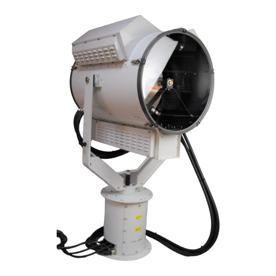
5-Kilowatt Xenon Searchlight
Product Reference Number:
A7290 – FX560RC 5Kw 440v 3 phase 50/60Hz
Manufacturer's details:
Francis Searchlights Ltd
Union Road, Bolton
Lancashire, BL2 2HJ, UK
Tel:
+44 (0) 1204 558960
Fax:
+44 (0) 1204 558979
http://www.francis.co.uk
E-mail: sales@francis.co.uk
Manual Part Number: C29238
Issue: 1
3.8.21
Distributor details:
Advertisement
Table of Contents

Related Manuals for Francis FX560RC


Summary of Contents for Francis FX560RC
- Page 1 User Instruction & Installation Manual FX560 Remote Control 5-Kilowatt Xenon Searchlight Product Reference Number: A7290 – FX560RC 5Kw 440v 3 phase 50/60Hz Manufacturer’s details: Distributor details: Francis Searchlights Ltd Union Road, Bolton Lancashire, BL2 2HJ, UK Tel: +44 (0) 1204 558960...
-
Page 2: Table Of Contents
CONTENTS - Introduction - Safety Precautions - Technical Information - Unpacking and Installation Instructions - Electrical Installation - Operating Instructions - Fault Finding - Maintenance and Servicing - General Assembly & Wiring Diagrams - Spare Parts List... -
Page 3: Introduction
For your future reference please keep this manual in a safe place. Thank you for specifying a product from the Francis Searchlights range. All Francis products are designed to give complete customer satisfaction and are manufactured to the highest engineering standards to ensure optimum performance and service life. -
Page 4: Safety Precautions
2 - Safety Precautions The following instructions must be adhered to, to ensure a safe working environment and the safety of the user. Note: When unpacking or manoeuvring the searchlight into its fixing position, suitable lifting points must be used to prevent damage to the equipment or personal injury. ◼... -
Page 5: Technical Information
3 - Technical Information This product has been designed to operate in accordance with the product specification. The FX560RC 5Kw searchlight has the following features: ◼ All marine grade materials and fixings. ◼ Electronic power supply unit. ◼ Instant re-strike no cooling down time. - Page 8 Remove front panel for AC & DC wiring connections. Back To Top...
- Page 9 (INPUT) 4 CORE 2.5mm TE2 50mm WELDING CABLE S50 2 CORE 1.5mm (D1)
-
Page 11: Unpacking And Installation Instructions
4 - Unpacking and Installation Instructions The following instructions should be read and fully understood prior to installing the equipment to ensure that the correct procedures are followed, and all safety precautions are observed. Note: If the equipment has been in storage for a considerable amount of time, it is advisable to conduct a routine maintenance check on all parts before installation. -
Page 12: Electrical Installation
5 - Electrical Installation Note: ~ When the main power is first applied to the searchlight, the searchlight will carry out a self-test, it will Pan to the left limit and Tilt down to the limit, once this is complete, the searchlight will then move to the centre and horizontal, during this please do not try and operate the searchlight while this test is being carried out. - Page 13 Installation Guidelines A typical installation and connection routine for the FX560RC searchlight is as follows: Referring to wiring diagram C29237, a supply is fed to the power supply unit, which then provides a common feed to the motor gearbox, searchlight, and joystick panel.
- Page 14 Fitting instructions for the 5Kw xenon lamp Referring to the diagram overleaf: Unfasten ten latches (A) on the front and rear of the searchlight. Remove the front bezel (B) and rear bezel (C) assemblies. Unscrew the two M6 hexagon screws (D) from the front lampholder mounting block (E) and remove the front lampholder assembly from the mounting bracket.
-
Page 16: Operating Instructions
6 - Operating Instructions This equipment is designed for use out of doors, in free air. Never place anything on or cover the searchlight when in use as this may present a hazard. Switch On The panel is activated using the PANEL button. This will illuminate brightly when the panel is active. - Page 17 seconds. Tilt up motion will now be inhibited above the current position. Clear Motion Limits Motion limits as set above can be cleared by switching the panel off then pressing and holding the focus button and lamp buttons together for 10 seconds. Adjusting Panel Illumination The panel illumination and indicators intensity can be adjusted to suit ambient light levels.
- Page 18 7. Anti-condensation heater output over current. – The 24VDC anti condensation heater output is taking excessive current. The heater output will switch off. To restore this output, remove the supply from the speed control card for a period. 8. Limit Switch Error. Some lamp types do not use all or some limit switches.
- Page 19 Setting to Work Safe service in use necessitates the strict observance of the following precautions. ◼ Any article fabricated from quartz or glass is inherently fragile and care should therefore be taken, always, when handling lamps. ◼ Eye protection must be worn when handling lamps that have been removed from their packaging materials.
- Page 20 Notes: 1) Xenon lamps are designed for dc operation only. The dc current may only be varied within the limits of the current control range. Xenon lamp operates best at rated current; over the life of the lamp, the current may be increased to its maximum value to compensate for loss of light.
- Page 21 FBUS SPEED CONTROL ASSEMBLY DETAILS MAINS CONNECTORS Live. Neutral Earth TILT CONNECTOR Tilt Motor Red Wire (+) Tilt Motor Black Wire (-) Tilt Encoder Red Wire (5V). (Voyager Brown Wire) Tilt Encoder Green Wire (Phase A Output) (Voyager Yellow Wire) Tilt Encoder White Wire (Phase B Output) Tilt Encoder Black Wire (Voyager Blue Wire) Tilt Limit Switch Common Black Wire...
- Page 22 FBUS Speed Control Board...
- Page 23 CONNECTIONS TO FBUS JOYSTICK CONTROL PANEL FBUS CONNECTOR OV Supply Input Line Terminate (Connect to + for terminate) FBUS + RS485 Data In/Out FBUS - RS485 Data In/Out +24V Supply Input JOYSTICK CONNECTOR Joystick Black Wire Joystick Yellow Wire Joystick Blue Wire Joystick Red Wire FBUS JOYSTICK CONTROL BOARD...
- Page 24 FBUS ADDRESS SWITCHES OVERVIEW SETTING LAMP ADDRESS VALUE The lamp address is set with the address switches using simple binary input. Each switch has a binary value as details below; - SWITCH 10 = 1 SWITCH 9 = 2 SWITCH 8 = 4 SWITCH 7 = 8 SWITCH 6 = 16 The address value is the sum of the numbers above which are active when...
- Page 25 EXAMPLES Standard control panel – panel address set to 5. Switch 1 = Off Switch 2 = On (Value 4 added to address) Switch 3 = Off Switch 4 = On (Value 1 added to address) 4 + 1 = 5 Speed control card - lamp address set to 11.
- Page 26 FBUS DATA PROTOCOL OVERVIEW The Francis bus (FBUS) is a custom communication protocol based on RS485 two wire bi-directional communication hardware. The system provides a simple bi-directional link between lamps and lamp control panels. The system allows given panels to communicate with different lamps and also allows a number of panels to communicate with the same lamp.
- Page 27 A detailed description of panel and lamp data follows. PANEL TRANSMITTED DATA Panels only send data when there is data to be sent i.e., there has been activity at the panel which must be sent to a given lamp. If there is no data to be sent, a panel will not transmit.
- Page 28 DATA_FOCUS_BUTTON (Hex 0B) This is a single byte command. When the lamp receives this, it will run the focus motor as long as the command remains. A panel will send this command so long as the focus button is pressed. DATA_HOME_BUTTON (Hex 0C) This is s single byte command.
- Page 29 DATA_TILT_POSITION (Hex 19) This is a three-byte command. Following the DATA_TILT_POSITION command two data bytes specify the position to which the lamp must move. The bearing resolution is 0.1 degrees. The value is sent LSB first with the first byte representing the lower position command bits. The MSB (sent last) lower 4 bits represents the remaining value.
- Page 30 The CRC is a simple data checking system. Basically, this is just the sum of the lamps address and bytes above. The value is radix to 8 bits. If the lamp address was 0 (bus address value 16) and the pan and tilt were both at centre and the lamp was switched on and all other status bits were 0 the values would be Hex 110, 80, 80, 01.
- Page 31 4. Send pan value half speed = 128 + (64/2) = Hex A0 within 1mS. 5. Send CRC value, in this case Hex 116 + Hex 01 + Hex A0 = 1D7 after radix to 8 bits = B7. 6. This completes the transmission. RECEIVING FROM A LAMP Lamps broadcast data sequentially.
- Page 32 DMX NORMAL OPERATION When the system is operating from DMX the status indicator will flash green slowly when DMX data is present. If no DMX data is present the LED will be static green. OPERATION DURING FAULTS During faults normal status LED operation is overridden. The status LED will flash red a number of times with the number of flashes corresponding to the specific fault.
- Page 33 OVERVIEW FBUS Control facilitates control of up to 12 searchlights from a PC. The system communicates to Francis Searchlights FBUS data system using one or more FBUS Interface units. Communication between the PC and FBUS interface can be RS485, RS422, USB (VCP) or UDP.
- Page 34 COMMUNICATION SETTINGS Settings must be configured to suit the application. For systems where FBUS Control communicates with the FBUS Interface via a serial link (RS422, RS485 or USB), the USE SERIAL PORT tick box should be checked. The desired com port can now be selected. To find the correct com port, set the FBUS interface to the correct communication protocol and set the data rate to 9600K.
- Page 35 To configure the system set LAMP BUTTON No to 1. Enter 000.000.000.001 for the IP address. Set FBUS LAMP No to 0. Change LAMP BUTTON No to 2 and set IP address to 000.000.000.001. Set FBUS LAMP No to 1. Now set LAMP BUTTON No to 3 and enter IP address 000.000.000.002.
- Page 36 LAMP ON / OFF Buttons These switch the lamp on and off. The 'LAMP ON' button will illuminate red to indicate when the lamp is switched on. If the DUAL HEAD option in SETTINGS is set, there will be lamp on off button for each lamp head. If the currently selected lamp is switched on or off from a different control station the lamp on the LAMP ON button will change to indicate the current lamp status.
- Page 37 VIRTUAL JOYSTICK The virtual joystick is the dark grey circle near the bottom left of the FBUS Control window. The virtual joystick facilitates lamp pan and tilt movement. To move the lamp up (Tilt up) move the mouse over the yellow dot at the centre of the virtual joystick.
- Page 38 FBUS INTERFACE UNIT (if supplied) OVERVIEW Francis Searchlights FBUS data system facilitates control of up to 30 searchlights from multiple control stations. To provide the required control response whilst maintaining a low data rate for extended transmission distance, the FBUS data system involves precisely timed control signals.
- Page 39 OPERATOR INTERFACE Four buttons control a simple menu system with a 2-line LCD display. A given menu item is selected with the SEL (select) button. If the menu item has an adjustable parameter this can be altered using the up and down arrow keys. The revised parameter is stored using the ENT (enter) button.
- Page 40 SET PAN ANGLE For system development and testing, this command sends a move to pan position command to the currently selected lamp. The pan angle is set using the arrow keys. Pressing ENT will move the lamp to the displayed angle. SET TILT ANGLE For system development and testing, this command sends a move to tilt position command to the currently selected lamp.
- Page 41 IP ADDR (UDP Only) This displays the interface units IP address. To change the IP address press ENT. Note that the system must use static IP addressing. GATEWAY ADDRESS (UDP Only) This is a diagnostic tool to display IP address of the gateway if applicable. EXTERNAL DATA INTERFACE –...
- Page 42 DATA_LAMP2_BUTTON (0x12) Four-byte command (Sync, Lamp address, command, CRC). Switches the lamp second head state (if fitted) from on to off or off to on. DATA_FOCUS2 BUTTON (0x13) Four-byte command (Sync, Lamp address, command, CRC). operates the head 2 focus motor momentarily (if fitted). To keep the focus motor running the command must be sent repeatedly.
- Page 43 DATA_MOVE_TO_PAN_POSITION (0x18) Six-byte command (Sync, Lamp address, command, Pan LSB, Pan MSB, CRC). Commands the selected lamp to move to a specified pan position. The position value is centred on a value of 2048. Values below 2048 represent negative angles, values above 2048 represent positive values. The resolution is 0.1 degrees.
- Page 44 Note that these commands are maintained. Sending a command once will cause motion to start at the specified speed. This will continue until a command is sent with a zero (128) speed value. DATA_POSITION (0x33) Seven-bytes (Sync, Lamp address, Pan low, Pan high, Tilt low, Tilt high, CRC).
- Page 45 DATA_FOCUS_ON (0x35) Four-byte command (Sync, Lamp address, command, CRC). Sets the focus motor running. Focus will continue to operate until a DATA_FOCUS_OFF command is received. This command is included to allow systems which have a low refresh rate to control the focus motor. DATA_FOCUS_OFF (0x36) Four-byte command (Sync, Lamp address, command, CRC).
-
Page 46: Fault Finding
7- Fault Finding All fault finding must be conducted by a competent person or qualified Electrical Engineer. Please refer to the following table for the troubleshooting of Xenon lamps. Fault Cause Remedy ◼ Wrong Polarity ◼ Lamp incorrectly fitted ◼ Anode (large electrode) ◼... - Page 47 4) If no supply is present, there is a fault in the motor gearbox. This should be examined and rectified accordingly. Note: If a fault occurs on the motor gearbox, the unit should be returned to Francis Searchlights Limited for fault evaluation and repair.
-
Page 48: Maintenance And Servicing
8 - Maintenance and Servicing To prolong the service life and performance of your searchlight, the following maintenance guidelines are recommended: ◼ Maintenance checks should be conducted before every voyage or at least every three months. ◼ Before checking, disconnect the equipment from the supply. ◼... -
Page 49: General Assembly & Wiring Diagrams
9 – General Assembly & Wiring Diagrams Drawing Number Description A7290 FX560RC 5Kw G.A. Wiring Schematic C29237 Wiring Diagram C27312 Joystick Panel Assembly C29195 Interface Output Enclosure Assy C29203 Junction Box Assy C29078 Interface Input Enclosure Assy C29209 5Kw PSU Cover Assy... -
Page 58: Spare Parts List
10 - Spare Parts List The following spare parts can be ordered directly from the manufacturer: Searchlight Spares Part Number Description C28671-00 Power Supply Unit C29254-01 Fan Assy (PSU Cover) C12081-00 Ignitor C24950-00 Fan (Searchlight Head) C24951-00 Capacitor C29221-01 Top Canopy Filter C29215-01 Bottom Vent Box Filter C26394-00... - Page 59 To prolong the life and performance of your product, we recommend that you only specify Francis Searchlights spare parts. This will ensure that any warranties on your equipment will not be invalidated. When ordering spare parts please contact the Sales Department at Francis Searchlights Limited.
Need help?
Do you have a question about the FX560RC and is the answer not in the manual?
Questions and answers