Advertisement
Quick Links
Advertisement

Related Manuals for KEP P295


Summary of Contents for KEP P295
- Page 1 P295 Installation & Operating Instructions 99795 12/16/10...
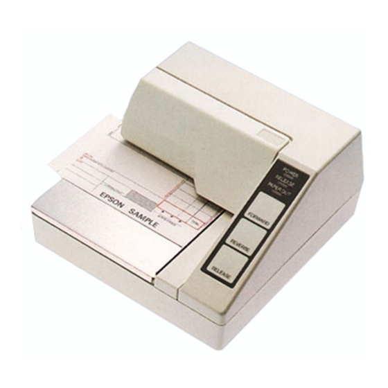
- Page 2 (1) Upper case (2) Printer cover (3) Operation panel (4) Document table (5) POWER switch (6) Interface connector (7) FG (8) Drawer kick-out connector (9) Power connector (I 0) DIP switches (I 0) (7) (8) (9) P295 P295P...
- Page 3 The illustration below shows the items included for the standard specification printer. If any item is damaged, please contact your dealer for assistance. • Note: See the Note on page 1-3 for information about the screws. Installation 1-1...
- Page 4 The printer is protected during shipping by a transportation damper that must be removed before you turn on the printer. 1. Pull the damper out and remove the strip of tape from the top of the printer, as shown below. Note: steps: turn on the printer, press the RELEASE button, press the FORWARD button, turn off the printer, and put the transportation...
- Page 5 P295 You need an appropriate serial interface cable to connect your computer to the printer. 1. Make sure that the printer and the computer are turned off. Then plug the cable into the connector on the back of the printer, as shown.
- Page 6 Connect the other end of the cable to the connector on your computer. P295 You need an appropriate parallel interface cable to connect your computer to the printer. Make sure that the printer and the computer are turned off. Then plug the cable into the connector on the back of the printer, as shown.
- Page 7 Plug the drawer cable into the drawer kick-out connector on the back of the printer next to the computer interface connector. P295 P295P Do not connect a telephone line to the drawer kick out connector. Installation 1-5...
- Page 8 AWG 18 or equivalent Diameter of terminal to be attached: Make sure that the printer is turned off. Connect the ground wire to the printer using the FG screw on the back of the printer, as shown. P295 P295P Installation 1-7...
- Page 9 Make sure that the power supply is turned off. Plug the power supply's cable into the printer's connector as shown below. Note that the flat side of the connector faces P295 P295P Plug the power cord into an outlet. Installation...
- Page 10 Be sure to use a ribbon cassette that meets the printer's specifications. The EPSON ERC-27 is recommended. • Note: For instructions on replacing a used ribbon, see Chapter 2. 1. Turn the printer on using the power switch on its left side. Press the RELEASE button to turn the light on.
- Page 11 Be sure to perform the steps above because it is necessary to make sure that the printer is in the paper release mode before you install the ribbon cassette. Open the printer cover by slightly pressing the ridges on the top left and pulling the cover forward, as shown in the illustration below.
- Page 12 Carefully insert the ribbon cassette in the printer as shown in the illustration below. Notice exactly where the ribbon must go. Then push firmly on the right side and then the left side of the ribbon cartridge until each side clicks into place. Installation 1-11...
- Page 13 Insert the paper from either the front or the side, as shown in the illustration below. Insert the paper into the printer until it is stopped by the form stopper. The markings on the side of the printer can also be used to judge how far to insert paper. 5.
- Page 14 3. While holding down the RELEASE button, turn the printer back on. Remove your finger from the RELEASE button. The printer prints the current printer settings and then eject the paper. 5. Press the RELEASE button to eject the paper completely and insert new paper to begin the second part of the test.
- Page 15 Turn the printer over and locate the DIP switches, as shown below. Notice that ON is marked on the set of switches. Use tweezers or another narrow tool to move the switches. Use the following tables to set the DIP switches.
- Page 16 P295 Switch Function Ignored Prints'?' Data reception error 512 bytes Receive buffer capacity 35 bytes XON/XOFF DTR/DSR Handshaking 7 bits 8 bits Word length Parity check Even Parity selection See Transmission Speeds table below, Not used Pin 6 reset signal...
- Page 17 The control panel has three buttons and three lights. Buttons All three of these buttons can be disabled or enabled by the ES C c 5 command. RELEASE Pressing this button moves the rollers so that paper can be inserted or removed. REVERSE Feeds the paper backward based on the line feed amount set by ESC 2 and ESC 3.
- Page 18 RELEASE This light is on when the printer is in the paper release mode and it is off when the printer is in the clamp mode. Paper can be inserted only when the printer is in the paper release mode. This light blinks to indicate an error condition in the following cases: •...
- Page 19 Then remove the used ribbon by grasping the handle and pulling straight out, as shown by the arrow in the illustration below. Then follow the rest of the steps in "Insatlling the Ribbon" in Chapter 1. Using the Printer 2-3...
-
Page 20: Power Problems
This chapter gives the solutions to some printer problems. Power Problems The POWER light does not come Make sure that the power supply cables are correctly plugged into the printer, the power unit, and to the power outlet. Make sure that power is supplied to the power outlet. If the outlet is controlled by a switch or timer, use another outlet. - Page 21 Impact dot matrix Printing Method: 7-pin shuttle type Head Wires Unidirectional Printing Direction: Lines per second 5 x 7 font: 1.9 to 2.3 7 x 7 font: 1.9 to 2.3 Characters per line 5 x 7 font: 35 7 x 7 font: 42 5 x 7 font: ANK: 0.63 Characters per inch: Graphics: 0.315...
- Page 22 Character size: 5 x 7 font: ANK: 1.6 mm (.063") x 2.9 mm (.114") Graphics: 1.9 mm (.075") x 2.9 mm (.114") 7 x 7 font: ANK: 1.3 mm (.051") x 2.9 mm (.114") Graphics: 1.6 mm (.063") x 2.9 mm - (.114") 4-2 Reference Information...
- Page 23 Papertype: Normal (high quality), pressure sensitive, and carbon copy papers Total thickness: Single Ply Paper: 0.09 to 25mm (.0035" to .0098") Copy Paper: 0.09 to 0.35mm (.0035" to .0138") Paper size: 80 mm (W) x 69 mm (L) to 182 mm (W) x 257 mm (L) 13-15'-'x 2.72,"' to 7.17"' x 10.12"") Up to the European B5 size.
-
Page 24: Notes On Slip Paper
Copy capability and Copying capability is influenced by ambient temperature the ambient temperature. Printing for printing: must be performed under the conditions, described in a Table below: Relationship between ambient temperature and number of copies Number of copies Ambient temperature (print mode) 5º... -
Page 25: Printing Position
Printing position ò Reverse Paper Feed ñ Forward Paper Feed Notes The mechanical form stopper is adjustable in the range 26.5 to 36.5 mm (1.04" to 1.44") The TOF and BOF sensors are fixed and cannot be adjusted. 3. After slip paper is set at the mechanical form stopper, the top margin can be shortened up to 21.2 mm (.83") by feeding the paper backwards (ejection feeding). -
Page 26: Electrical Specifications
Electrical Specifications Supply voltage: +24 VDC ± 10% Mean - approx. Current consumption: Operating 600 mA at 24 (except for VDC (full-column drawer kick- printing and data out): transmission of ANK characters) Peak - approx. 5.5 A at 24 VDC (full- column printing and data transmission of ANK characters) - Page 27 Reliability 3,000,000 lines Life: Mechanism: Print head: million characters (when in the average of 2 dots/wire per character.) • End of Life is defined as the point at which the printer reaches the beginning Wearout Period. 180,000 hours MTBF: • Failure is defined as Random Failure occurring at the time of the Random Failure Period.
-
Page 28: Environmental Conditions
Environmental Conditions Temperature: Operating: 5º to 40ºC (41º to 104ºF) -I0º to 50ºC (14º Storage: to 122ºF) (except for ribbon and paper) Humidity: Operating: 30 to 85% (with no condensation) Storage: 30 to 90% (with no condensation, except for ribbon and paper) Serial interface: RS-232...
Need help?
Do you have a question about the P295 and is the answer not in the manual?
Questions and answers