
Summary of Contents for versa VX-GPU2610-9
- Page 1 VX-GPU2610-9 L2+ Managed GbE PoE+ Switch Quick Installation and Initial Configuration...
-
Page 2: Table Of Contents
Contents Chapter 1 Introduction ..........1 Overview ................... 1 Front View of the Switch ............1 Rear View of the Switch .............. 1 LED Descriptions ................2 Mode/Reset Button ..............4 Chapter 2 Installing the Switch......5 Package Contents ................. 5 Mounting the Switch on Wall .......... -
Page 3: Chapter 1 Introduction
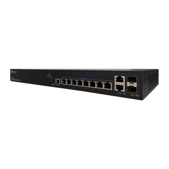
Overview This user guide describes how to install, configure, and troubleshoot the VX-GPU2610-9, 10 Ports L2+ Managed GbE PoE+ Switch. By reading this user guide, users can perform the following tasks: To check the switch status by reading the LED behavior •... -
Page 4: Led Descriptions
LED Descriptions The LEDs on the front panel provide users with switch status checking and monitoring. There are three types of LEDs as follows: System LED • indicates if the switch is powered up correctly or not. Mode LEDs • indicates the mode of all ports on the switch. - Page 5 By pressing the Mode button in less than 2 seconds to change LED modes (Link/Act/Speed Mode or PoE Mode), users can check the port status by reading the LED behaviors per the table below. Table 3: Port Status LEDs When Link/Act/Speed Mode LED Lit LED Color State Description...
-
Page 6: Mode/Reset Button
Mode/Reset Button By pressing the Mode/Reset Button for certain period of time, users can perform the following tasks. Change Port Status LED Mode • to read the port status correctly in the two different modes (Link/Act/Speed mode or PoE mode). Reset the Switch •... -
Page 7: Chapter 2 Installing The Switch
Chapter 2 Installing the Switch Package Contents The Switch • AC Power cord (Option) • Four adhesive rubber feet • Installation Guide • RJ45 to DB9 Serial Console Cable (Option) • Note: The switch is an indoor device. If you need to use it to connect outdoor devices such as outdoor IP cameras or outdoor WiFi Aps with cable, then you need to install an arrester on the cable between outdoor device and the switch. -
Page 8: Mounting The Switch On Wall
Mounting the Switch on Wall Step 1: stall user-supplied screws on the appropriate location on the all, and be aware of the dimensional limitation of the screws. Figure 3: Install screws to the wall Step 2: make sure that the switch is attached securely to wall. Figure 4: Attaching switch to the wall Mounting the Switch on Desk or Shelf Step 1:... -
Page 9: Connecting The Ac Power Cord
Figure 5: Attaching the Rubber Feet Connecting the AC Power Cord Step 1: Connect the AC power cord to the AC power receptacle of switch. Step 2: Connect the other end of the AC power cord to the AC power outlet. -
Page 10: Installing Sfp Modules
Installing SFP Modules You can install or remove a mini-GBIC SFP module from a SFP port without having to power off the switch. Step 1: Insert the module into the SFP port. Step 2: Press firmly to ensure that the module seats into the connector. Figure 7: Installing a SFP Module into a SFP Port Note The SFP ports should use UL Listed Optional Transceiver product, Rated... -
Page 11: Chapter 3 Initial Configuration Of Switch
Chapter 3 Initial Configuration of Switch Initial Switch Configuration Using Web Browsers After powering up the switch for the first time, you can perform the initial switch configuration using a web browser. For managing other switch features, please refer to the Web interface user guide for details. To begin with the initial configuration stage, you need to reconfigure your PC’s IP address and subnet mask so as to make sure the PC can communicate with the switch. - Page 12 Step 2: Select Network and Sharing Center Step 3: Click on Change adapter settings on the left of PC screen Note Users can also skip step 1 to 3, by pressing WinKey+R and type ”ncpa.cpl” command to get to step 4 directly. Step 4: Right-click on your local adapter and select Properties Step 5:...
- Page 13 If your PC is configured correctly, you will see the login page of the switch as shown by Figure 9 below. Figure 8: Web Interface login page If you do not see the above login page, please perform the following steps: - Refresh the web page.
-
Page 14: Chapter 4 Troubleshooting
Chapter 4 Troubleshooting The following table provides information for users to easily troubleshoot problems by taking actions based on the suggested solutions within. Table 5: Troubleshooting Table Possible Symptoms Suggested Solutions Causes 1. Check if correct power cord is connected firmly to the switch and to the AC outlet socket.
Need help?
Do you have a question about the VX-GPU2610-9 and is the answer not in the manual?
Questions and answers