Amana ACR2303MFW Owner's Manual
Freestanding
Hide thumbs
Also See for ACR2303MFW:
- Manual (12 pages) ,
- User instructions (12 pages) ,
- User instructions (12 pages)
Table of Contents
Advertisement
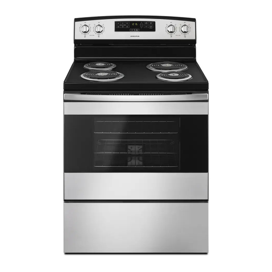
FREESTANDING ELECTRIC RANGE
Table of Contents
RANGE SAFETY.............................................................. 2
Range Safety ............................................................. 2
RANGE MAINTENANCE AND CARE................................... 4
Self-Cleaning Cycle (on some models) ............................ 4
General Cleaning........................................................ 4
INSTALLATION INSTRUCTIONS ........................................ 6
REQUIREMENTS ............................................................. 6
Tools and Parts .......................................................... 6
Location Requirements ................................................ 7
Electrical Requirements - U.S.A. Only............................. 8
INSTALLATION ............................................................... 9
Unpack Range ........................................................... 9
Install Anti-Tip Bracket ................................................. 9
Electrical Connection - U.S.A. Only ............................... 11
Verify Anti-Tip Bracket Is Installed and Engaged .............. 15
Level Range ............................................................ 16
some models) .......................................................... 16
Storage Drawer (on some models) ............................... 17
Oven Door............................................................... 17
Complete Installation ................................................. 18
Moving the Range ..................................................... 18
IMPORTANT:
Save for local electrical inspector's use.
W11509598A
OWNER'S MANUAL
Advertisement
Table of Contents

Related Manuals for Amana ACR2303MFW


Summary of Contents for Amana ACR2303MFW
-
Page 1: Table Of Contents
FREESTANDING ELECTRIC RANGE OWNER’S MANUAL Table of Contents RANGE SAFETY.............. 2 Range Safety ............. 2 RANGE MAINTENANCE AND CARE........4 Self-Cleaning Cycle (on some models) ......4 General Cleaning............4 INSTALLATION INSTRUCTIONS ........6 REQUIREMENTS ............. 6 Tools and Parts ............6 Location Requirements .......... -
Page 2: Range Safety
RANGE SAFETY Your safety and the safety of others are very important. We have provided many important safety messages in this manual and on your appliance. Always read and obey all safety messages. This is the safety alert symbol. This symbol alerts you to potential hazards that can kill or hurt you and others. All safety messages will follow the safety alert symbol and either the word “DANGER”... - Page 3 IMPORTANT SAFETY INSTRUCTIONS � Do Not Leave Children Alone - Children should not be left � Do Not Soak Removable Heating Elements – Heating alone or unattended in area where appliance is in use. elements should never be immersed in water. They should never be allowed to sit or stand on any part �...
-
Page 4: Range Maintenance And Care
RANGE MAINTENANCE AND When “ ” shows in the display, the door of the oven cannot be opened. To avoid damage to the door, do not force the door open CARE when “ ” is displayed. Self-Cleaning Cycle (on some Before self-cleaning, make sure the door is completely closed or the door will not lock and the Self-Cleaning cycle will not begin. - Page 5 STAINLESS STEEL (on some models) 3. Polish with a clean, dry cloth or a clean, dry paper towel. NOTE: To avoid damage to stainless steel surfaces, do not use soap-filled scouring pads, abrasive cleaners, Cooktop Cleaner, steel-wool pads, gritty washcloths, or abrasive paper towels. Damage may occur to stainless steel surfaces, even with one-time or limited use.
-
Page 6: Installation Instructions
Parts supplied SURFACE UNDER COOKTOP (on some models) The coil cooktop will lift up to provide easy access for cleaning Check that all parts are included. beneath. Lift the cooktop by both front corners until the support � 3 - 10-32 hex nuts (attached to terminal block) locks into place. -
Page 7: Location Requirements
Location Requirements Cabinet Dimensions Cabinet opening dimensions shown are for 25" (64.0 cm) IMPORTANT: Observe all governing codes and ordinances. countertop depth, 24" (61.0 cm) base cabinet depth and � It is the installer’s responsibility to comply with installation 36" (91.4 cm) countertop height. clearances specified on the model/serial/rating plate. -
Page 8: Electrical Requirements - U.s.a. Only
Electrical Requirements – U.S.A. ** If connecting to a 50 A circuit, use a 50 A rated cord with kit. For 50 A rated cord kits, use kits that specify use with a nominal 1 " Only (34.9 mm) diameter connection opening. If codes permit and a separate ground wire is used, it is �... -
Page 9: Installation
INSTALLATION On Ranges Equipped with a Warming Drawer or Premium Storage Drawer: Unpack Range On ranges equipped with a warming drawer or premium storage drawer, the rear legs cannot be accessed by removing the warming drawer or premium storage drawer. It will be WARNING necessary to adjust the rear legs from outside the range. - Page 10 3. Determine and mark centerline of the cutout space. The 5. Using the Phillips screwdriver, mount anti-tip bracket to the mounting can be installed on either the left-side or right-side of wall or floor with the two #12 x 1 "...
-
Page 11: Electrical Connection - U.s.a. Only
Electrical Connection - U.S.A. Only Power Supply Cord Direct Wire WARNING WARNING Electrical Shock Hazard Electrical Shock Hazard Disconnect power before servicing. Disconnect power before servicing. Use a new 40 amp power supply cord. Use 8 gauge copper or 6 gauge aluminum wire. Plug into a grounded outlet. - Page 12 � Tighten strain relief screw against the power supply cord. And you will be If your home has: Go to Section: connecting to: 3-wire receptacle A UL Listed, 250 V 3-wire connection: (NEMA type 10-50R minimum, 40 A, Power supply cord range power supply cord 3-wire direct...
- Page 13 5. Use 3/8" (9.5 mm) nut driver to connect the neutral (white) 2. Use 3/8" (9.5 mm) nut driver to connect the neutral (white) wire to the center terminal block post with one of the 10-32 wire to the center terminal block post with one of the 10-32 hex nuts.
- Page 14 1. Part of metal ground strap must be cut out and removed. Bare Wire Torque Specifications Attaching terminal lugs to the terminal block - 20 lbs-in (2.3 N-m) Wire Awg Torque 8 gauge copper 25 lbs-in (2.8 N-m) 6 gauge aluminum 35 lbs-in (4.0 N-m) 5.
-
Page 15: Verify Anti-Tip Bracket Is Installed And Engaged
Verify Anti-Tip Bracket Is Installed 2. Attach terminal lugs to line 2 (red), bare (green) ground, and line 1 (black) wires. Loosen (do not remove) the setscrew on and Engaged the front of the terminal lug and insert exposed wire end through bottom of terminal lugs. -
Page 16: Level Range
Level Range Warming Drawer or Premium Storage Drawer (on some models) ® Determine if you have AquaLift Technology or Steam Clean by referring to the “Range Maintenance and Care” section. Remove all items from inside the warming drawer or premium For Ranges with AquaLift ®... -
Page 17: Storage Drawer (On Some Models)
Storage Drawer (on some models) Oven Door The storage drawer can be removed. Before removing, make sure For normal range use, it is not suggested to remove the oven drawer is cool and empty. door. However, if removal is necessary, make sure the oven is off and cool. -
Page 18: Complete Installation
Moving the Range Complete Installation 1. Check that all parts are now installed. If there is an extra part, go back through the steps to see which step was skipped. WARNING 2. Check that you have all of your tools. 3.
Need help?
Do you have a question about the ACR2303MFW and is the answer not in the manual?
Questions and answers