
Related Manuals for UCL SWIFT KR12

Summary of Contents for UCL SWIFT KR12
- Page 1 Optical Fiber Arc Fusion Splicer Read this user manual carefully before running KR12 SWIFT KR12 USER MANUAL WWW. UCLSWIFT.COM...
- Page 2 This device complies with Part 15 of the FCC Rules. Operation is subject to the following two conditions: (1) This device may not cause harmful interference, and (2) this device must accept any interference received, including interference that may cause undesired operation.
-
Page 3: Table Of Contents
4.2 Turn on the Swift KR12 4.3 Installing the sleeve loader 4.4 Cleaning the fiber 4.5 Inserting the fiber into the sleeve 4.6 Placing the fiber into the holder and stripping 4.7 Cleaving the fiber 4.8 Load the fiber to the Swift KR12 4.9 Splice... - Page 4 4.10 Removing the spliced fiber 4.11 Heating the sleeve V. MAINTENANCE 5.1 Cleaning and examination prior to splicing 5.2 Regular maintenance and cleaning VI. MENU 6.1 Splice 6.2 Heat 6.3 History 6.4 Option 6.5 Calibration 6.6 Electrode 6.7 Setting 6.8 Information VII.ERROR MESSAGE 7.1 Too Dirty Fiber 7.2 Replace The Fiber In The Correct Position...
- Page 5 7.7 Mismatch Fiber Number 7.8 Core Bubble Error 7.9 Gap Limit Over VIII.HOW TO DEAL WITH SPLICING PROBLEMS 8.1 When the splice loss is too high 8.2 Abnormal operation of arc fusion splicer IX. Q & A 9.1 Power 9.2 Splice 9.3 Sleeve heater 9.4 The others X.
-
Page 7: For Your Safety
The Swift KR12 is designed to satisfy the user’s convenience for both outdoor and indoor use, allowing the operation easy and simple. Still, we strongly recommend our customers to read this user manual carefully prior to running the Swift KR12 in order to prevent any accident and breakdown because improper handling may cause danger. - Page 8 Connect the supplied AC power cord to the battery. Check to ensure no dust or foreign substance on the AC plugs before connecting it. Unsafe connection may cause the fumes, fire or damage to the Swift KR12 and result in serious personal injury or death.
- Page 9 Using a damaged power cable may result in fire or personal injury. Connect 3-core AC power cord. DO NOT use 2-core, cable and plug. DO NOT touch the AC plugs, AC power cable or the Swift KR12 with wet hands. It may cause an electric shock.
- Page 10 DO NOT clean the Swift KR12 using compressed air or gas. Please check the shoulder belt before transporting. Transporting the case with a damaged shoulder belt, it may cause the damage of the Swift KR12 and the personal injury. Make sure to wear protective glasses while performing splicing works. If the fiber fragments come into contact with the eye or skin, it can be extremely dangerous.
- Page 11 DO NOT place the Swift KR12 in an unstable or unbalanced position. The machine may fall, causing injury or damage to the Swift KR12. The Swift KR12 is precisely adjusted and aligned. DO NOT allow the unit to receive a strong impact. Use supplied carrying case for its transportation and storage.
-
Page 12: Specifications
II. Specifications 2.1 General specifications Subject Description Fiber alignment Ribbon SM(G.652), MM(G.651), DS(G.653), NZDS(G.655), Applicable fibers SM(G.657) Fiber count Single fiber, 2~12 Ribbon fiber Single: Cladding diameter 125μm, Coating diameter Applicable fiber 250, 900μm dimensions Ribbon: Cladding diameter 125μm, Ribbon fiber thickness 0.25 to 0.40mm Fiber cleave length 10mm... -
Page 13: Components
USB, External Power(DC 12V available for car cigar Terminals jack), DC Output 13.2~16.8V 2.1 Components 2.2.1 Standard items Description Model No. Quantity Arc Fusion Splicer Swift KR12 Download from UCL User guide Swift Website Spare electrode EI-28 1 pair Transporting Case Hard Case... - Page 14 Tool box USB Cable DC output Cable 2.2.2 Optional items Description Model No. Battery K3360(6000mAh) Cleaver Blade BI-07 Electrode EI-28 External Power DC 12V available for car cigar jack Sleeve R-F40 (40mm) Sleeve Clamp Sleeve Loader (2ea) H7-4-10, H7-8-10, H7-12-10, H7- 250-10, H7-900-10, H7-2.5-10, H7- Optical Fiber Holder IN-10, H7-2-10, H7-6-10, H7-10-10,...
-
Page 15: Product Description
III. Product Description 3.1 Function Buttons Button Description To turn the power on/off-press button for about 1.0 second. Press for about 1 second in POWER ON status, the LCD monitor turns off. Turn off the power after 2~3 seconds. To call the main menu screen. To execute splicing command. -
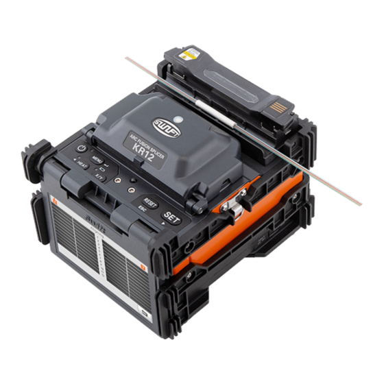
Page 16: Part Name Of Swift Kr12
3.2 Part name of Swift KR12 Sleeve Heater Windshield Cover Battery Monitor (Touch panel) - Page 17 Lock Lever WiFi Slot DC Out, Data Sync Remaining Battery Indicator Remaining Battery Indicator Button...
- Page 18 Heater Cover H-Connector Block Cooling Tray...
-
Page 19: Operation
The initial screen is displayed as below. It is important to choose a right splice mode and heat mode to ensure an accurate splicing result. The basic information of the Swift KR12 is displayed on the initial page. Before splice, make sure the appropriate mode is selected. - Page 20 Insert the battery into the battery groove until it clicks. Lock Lever Battery Pack Please make sure the power is off before removing the battery. Remove the battery by releasing lock lever.
- Page 21 10 seconds and connect again the DC cord to the DC jack. Swift KR12 can be charged during operation because the floating charging method is applied. The battery can be also charged with 12V Cigar jack charger.
- Page 22 4.1.3 How to check remaining battery capacity Press to check the remaining battery capacity. Remaining battery Remaining battery capacity display Percentage amount (Monitor) (LED) remains 80 ~ 100% 5 LED (5 bars) (4 bars) 60 ~ 80% 4 LED 40 ~ 60% (3 bars) 3 LED (2 bars)
-
Page 23: Turn On The Swift Kr12
4.2 Turn on the Swift KR12 Press and hold for about 1.0 second without opening the windshield cover. The initial screen is displayed as below after resetting all their initial functions. It is important to choose a right splice and heat mode to ensure an accurate splicing result. -
Page 24: Installing The Sleeve Loader
4.3 Installing the sleeve loader Get the sleeve loader installed as follows. 4.4 Cleaning the fiber Clean carefully the fiber with a piece of soft cloth or gauze soaked in alcohol. Dust on the fiber coating surface may increase attenuation and cause the fiber break after the heating of sleeve. -
Page 25: Inserting The Fiber Into The Sleeve
4.5 Inserting the fiber into the sleeve Insert the fiber into the sleeve. -
Page 26: Placing The Fiber Into The Holder And Stripping
4.6 Placing the fiber into the holder and stripping Place the fiber on the fiber holder as shown below. In the case of ribbon fiber, the color of each fiber should be matched each other left and right. Strip the fiber using by the manual stripper as shown below. - Page 27 The tip of the fiber should be removed after [arc calibration]. Otherwise, it may cause serious damage to the stripper blade. Clean carefully the fiber with a piece of soft cloth or gauze soaked in alcohol. Use high quality ethyl-alcohol with higher than 96% purity.
-
Page 28: Cleaving The Fiber
Cleaving the fiber i. Place the stripped fiber on the V-groove of the cleaver and check the length to cleave the fiber. Separate the each fiber when using the ribbon fiber. If the each fiber is not separated, it can make the problem on the cleaving. ii. -
Page 29: Load The Fiber To The Swift Kr12
4.8 Load the fiber to the Swift KR12 i. Open the windshield cover. Insert the fiber holder on the Swift KR12 ii. Make sure that the tip of the prepared fiber does not contact other object. iii. Place the other fiber in the same way as directed above. -
Page 30: Splice
The condition of the fiber can be observed via the image processing system in the Swift KR12. However, the visual inspection is necessary to ensure better splice result. The splicing process starts as soon as the windshields cover is closed in Auto mode. - Page 31 v. The splice result is stored as follows. The splice result is automatically stored when the splice is completed.
-
Page 32: Removing The Spliced Fiber
Open the cover of the left-fiber holder. v. Hold the both sides of the spliced fiber and remove the fiber from the Swift KR12 carefully not to break. 4.11 Heating the sleeve i. Move the center of sleeve to the splice point. Make sure the strength member in the sleeve is downward. -
Page 33: Maintenance
V. Maintenance 5.1 Cleaning and examination prior to splicing 5.1.1 Cleaning V-groove Any contaminants inside the V-groove will affect the splicing condition of the fiber, resulting in higher splice loss. Hence, it is important to inspect the V-groove often and clean it periodically in accordance with following ways. i. - Page 34 5.1.2 Cleaning the cleaver The performance of the fiber cleaver can be deteriorated if the blade or clamp pads of the cleaver are contaminated. In addition, the contamination of the fiber surface or tip can cause higher splice loss. For this reason, it is important to clean both the blade and clamp pads of the cleaver with a cotton swab soaked in alcohol.
-
Page 35: Regular Maintenance And Cleaning
Swift KR12. Therefore, the two objective lenses have to be cleaned on a regular basis. Otherwise, the dust sticks on the surface and it may become irremovable eventually. - Page 36 5.2.2 Blade replacement and blade mode (Rotating / Locking) Blade change If the cleaver does not properly cleave the fiber, rotate the blade as follow the instructions. On the blade gear, the channel (cleaving position) from 1 to 24 is marked.
- Page 37 ii. Remove blade pin completely using (-) driver. iii. Remove old blade with blade gear from body and replace new blade with blade gear. In here reassembling should be done in a reverse order of disassembling. At this time, especially be careful not to damage the blade. Check the blade operating condition with cleaver cover.
- Page 38 [Blade Mode(Rotating/Locking) Change] i. Blade rotating mode. Initial setting mode will be set as shown picture (Rotation mode). ii. Adjust gear pusher position after loosen Set-screw as shown picture. iii. Blade locking mode. When the blade is used without rotating.
- Page 39 5.2.3 Electrodes Replacement The recommended replacement cycle of an electrode is 3,000 times. If the real arc count exceeds the replacement cycle, a message for electrodes replacement appears. Without replacing the worn electrode, the splice loss increases and the spliced point becomes weaker. i.
-
Page 40: Menu
VI. Menu There are 8 sub menus in the main menu. To call a main menu, press . It can be selected by using or click the screen. The main menu is as below. Splice ü Del: delete splice mode. ü... - Page 41 ü Clear Arc Count: erase an arc count number. Setting ü Language: select a language. ü Date: set a current time. ü Power Save: set a sleep function of the Swift KR12. ü Volume: change a buzzer volume. ü LCD Brightness: change a monitor brightness. Information ü...
- Page 42 POP-UP Menu The pop-up menu is new feature of the Swift KR12. The purpose of the pop-up menu is to allow quick access to frequently used modes like splice mode and heat mode. The user can access the pop-up menu in various ways.
- Page 43 [Splice POP-UP Menu] How to add Press "Splice" for splice pop-up menu in the initial Ready state. Select Empty slot. iii. Select the splice mode.
- Page 44 How to delete Click Select mode to be deleted.
- Page 45 [Heat POP-UP menu] How to add Press "Heater" for heat pop-up menu in the initial Ready state. Select Empty slot. iii. Select the heat mode.
- Page 46 How to delete Click Select mode to be deleted.
-
Page 47: Splice
User splice mode: mode number 43 to 100 [Summary of Splice Mode] Splice mode Description The Swift KR12 identifies the number of fibers automatically. Users are not allowed adjusting arc AUTO discharge amount. AUTO mode consists of SM AUTO, MM AUTO, NZ AUTO, DS AUTO, G657 AUTO. - Page 48 G.657A1 is improved bending loss than basic SMF(G.652D) ~G657-12 MFD is 9~10um at near 1550nm. Other splice modes are saved in the Swift KR12 database. New splice modes will be continuously added to the Other database. Please contact UCLSWIFT Co., Ltd for the latest available splice modes.
- Page 49 6.1.3 New Click “New”, then the splice modes stored in memory is displayed on the screen. Select the splice mode, click “OK”. The selected splice mode is added the last blank mode. The splice mode from No.1 to No.42 can’t be added. 6.1.4 Edit Click “Edit”, then the splice parameters is displayed on the screen.
- Page 50 [Editable parameters in mode] Normal User Parameters Description mode mode The splice modes saved in the database are displayed. The mode selected by the Fiber type user is copied to the splice mode in the user side program. The title can be composed of 1 to 11 Mode title 1 characters.
- Page 51 carried out during the opening the Editable windshield after splicing or pressing RESET. A short period of arc discharge is performed to remove the fine dust on the Cleaning Power fiber surface as setting the distance between the cross sections of the fibers. Cleaning Time The duration of arc discharge is set.
- Page 52 [arc1] is set here. Editable Arc1 Time It sets the time of [arc1]. It is the second step of arc. [arc2] is set Arc2 Power here. It sets the time of [arc2]. In general, [arc2 time] is set to “OFF”. It is possible to set a very long arc time;...
- Page 53 It refers to the sum of the initially measured splice loss value and increased loss value. When splicing special types of the fiber or different kinds of the fiber, a higher splice loss can occur even under an Offset optimized arc discharge condition. The minimum value of the actual splice loss has to be set in order to accord the actual splice loss value with estimated splice loss...
-
Page 54: Heat
6.2 Heat In normal operation mode, to call the heat menu, press . Then you can see the heat menu as below. There’re already various heat mode and the user can select for proper operation. Also the heat mode will be stored up to 100. Please note that the user can’t use the Del and Replace keys and use Edit key partially from mode No 1 to No 8. - Page 55 The mode from No 1 to 8 can’t be replaced. 6.2.3 New Click “New”, then heat modes stored in memory is displayed on the screen. Select a heat mode, click “OK”. The selected heat mode is added the last blank mode. The mode from No 1 to 8 can’t be added.
- Page 56 6.2.4 Edit Click “Edit”, then heat conditions stored in memory are displayed on the screen. Select parameters, adjust it for proper operation. The heat mode from No.1 to 8 can’t be edited. 6.2.5 Select Click “Select”, then the selected heat mode is stored in the memory for operation. 6.2.6 Close Click “Close”...
-
Page 57: History
6.3 History In normal operation mode, to call the history menu, press . Then you can see the history menu as below. There’re already various functions to display data and image also copy such data to USB memory. 6.3.1 Display Memory The 10,000 both splice loss data and image can be stored and the user can see them. - Page 58 6.3.2 Clear memory Clear memory erases the whole data.
- Page 59 6.4 Option In normal operation mode, to call the option menu, press . Then you can see the option menu as below. There’re already various functions and whatever the user can select for proper operation. 6.4.1 Default Default is composed of 4 sub check boxes. To activate a Default menu, check a check box. Parameters Description Auto splice...
- Page 60 6.4.2 Lock Default is composed of 4 sub check boxes. To activate a Default menu, check a check box. Also it is possible to limit the modifications with respect to the total splice mode, heat mode, and internal memory data by setting up a password. You have to remember the password.
- Page 61 Enter a new password. iii. Confirm a new password. If an incorrect password is entered or you press a wrong button, the screen moves to upper level. You have to remember the password. If you forget the password, the device has to be brought to UCLSWIFT Co., Ltd to fix it.
-
Page 62: Calibration
6.5 Calibration In normal operation mode, to call the calibration menu, press . Then you can see the calibration menu as below. There’re already various functions to arc test, diagnostic test and motor drive test. 6.5.1 Diagnostic Test Diagnostic test executes various types of tests at a time. It is executed in the order Dust Test, LED Check. - Page 63 6.5.2 Motor Drive It checks the operating status of the motor manually. Place the fiber in the splicer. Click “Motor Drive”. iii. Touch screen to change motor selection. The name of the selected motor is displayed at the top left on the screen. to move the selected motor to a desired direction.
- Page 64 Arc calibration is a function to change the value of arc discharge voltage. It is used for the computation program for splicing. In addition, the calibration value of arc discharge cannot be changed in the splice mode. For the purpose of Arc calibration, 12 core or 8 core single mode fibers are used.
-
Page 65: Electrode
6.6 Electrode In normal operation mode, to call the Electrode menu, press . Then you can see the Electrode menu as below. It is necessary to regularly check and clean the electrodes because they are worn out. The silica oxidized substances is deposited as the electrodes go through numerous times of splices. - Page 66 iii. Click Perform 30 cycle continuous arc discharge to stabilize the electrodes. Result similar to following is displayed on the screen when measuring is completed. After completing the Electrode Stabilize, ARC Calibration should be performed separately. 6.6.2 Electrode Replace The recommended replacement cycle of an electrode is 3,000 times use. When the set cycle completes, a message to replace the electrode appears.
- Page 67 6.6.3 Electrode Caution It determines the arc count for alert message. The recommended replacement cycle of an electrode is 3,000 times use. 6.6.4 Electrode Used It displays the used arc count. 6.6.4.1 Clear Arc Count It erases the number of arc count. When insert new set of electrodes, please reset arc count.
-
Page 68: Setting
6.7 Setting In normal operation mode, to call the Setting menu, press . Then you can see the Setting menu as below. 6.7.1 Language It sets a language to be displayed on the screen. 6.7.2 Date It sets the date and time in the calendar. - Page 69 The monitor is turned on again when you press any button. 6.7.3.2 Splicer The Swift KR12 will be automatically turned off, if you don’t operate it for a time set. The Swift KR12 is turned on again only when you press...
- Page 70 6.7.4 Volume To adjust the buzzer volume. 6.7.5 LCD Brightness To adjust a monitor brightness.
-
Page 71: Information
6.8 Information In normal operation mode, to call the Information menu, press . Then you can see the Information menu as below. There is some information for your maintenance. 6.8.1 Maintenance Info Click “Maintenance Info”, following information is displayed. Item Description The date when equipment was manufactured Produce date... - Page 72 6.8.2 Sensor Value Click “Sensor Value”, following information is displayed. The splicer consists of various sensors including temperature, pressure and humidity. 6.8.3 Program Ver Click “Program Ver”, following information is displayed. The firmware is upgraded using USB memory.
- Page 73 6.8.4 HELP Click “HELP”, following help is displayed. Item Description The Name of Parts The main part of the Swift KR12 Clean and Inspect How to clean and inspect Warnings Warnings A/S Contact List Service contact point...
-
Page 74: Vii.error Message
VII. Error message 7.1 Too Dirty Fiber It is displayed when the fiber prepared for splice is contaminated more than normal status. How to: Reset the fiber after cleaning. 7.2 Replace The Fiber In The Correct Position It is displayed when the fiber is not placed in the middle of the electrodes and V- groove or the objective lenses or reflection mirror is contaminated. -
Page 75: Too Long Fiber
7.3 Too Long Fiber It is displayed when the fiber is placed too close to the electrode, the lenses or reflection mirror is dirty or LED light is not bright enough. How to: Press and place the fiber again. How to: Remove dust and dirt from the lenses and reflection mirror. How to: Conduct an LED test. -
Page 76: Fiber Is Not Placed In V-Groove
7.5 Fiber Is Not Placed In V-Groove. Please Place The Fiber Again. It is displayed when the fiber is not placed on the V-Groove. How to: Place the fiber again. 7.6 The Variation Of The Optical Fiber Core. To Cut Back The Fiber. It is displayed when the measured variation of the fiber length is greater than the limit. -
Page 77: Mismatch Fiber Number
7.7 Mismatch Fiber Number It is displayed when the number of fibers is not consistent with opposite side. How to: Check all the fibers are placed on the V-Groove. How to: Make sure broken fibers. How to: Check the splice mode is being used properly. 7.8 Core Bubble Error It is displayed when bubbles or dots exist in the spliced part after completing the splice. -
Page 78: Gap Limit Over
7.9 Gap Limit Over It is displayed when the measured gap of the fiber is greater than the limit. How to: Reset the fiber after checking the condition of the cleaver. -
Page 79: Viii.how To Deal With Splicing Problems
VIII.How to deal with splicing problems 8.1 When the splice loss is too high o It may have been caused by dirt or dust on the surface of fibers. Carefully clean the surface of the fibers DO NOT clean the fiber after being cleaved so as to prevent the contamination of its cross section. -
Page 80: Abnormal Operation Of Arc Fusion Splicer
8.2 Abnormal operation of arc fusion splicer o The alignment motion is repeated. Open and close the windshield cover again. Rest the system by pressing when an error occurs by opening the windshield cover. Turn off the power and contact UCLSWIFT Co., Ltd. -
Page 81: Q & A
IX. Q & A 9.1 Power o Unable to turn off the power by pressing Press the switch and hold it for about 1 second and release the button when the monitor is turned off. o Unable to splice as number of times as the splicer normally does with the battery that has been fully charged. -
Page 82: Splice
Charge the battery. o When the battery indicator provides wrong information. Use the indicator information only for your information. 9.2 Splice o When an error message appears on the screen. Refer to the [Error message list] for detailed information. o Irregular or higher splice loss. Clean the V-groove, V-block, reflection mirror and objective lenses referring to [Maintenance]. -
Page 83: Sleeve Heater
You cannot change arc amount and time in SM, NZ, MM or Auto mode. A proper arc discharge amount can be maintained in these modes by performing [Arc Calibration]. The Arc amount and time will set automatically to prevent from being changed in other mode. o How to set pause. -
Page 84: The Others
9.4 The others o How to lock “Splice”, “Edit” or heat mode? Refer to [Lock Menu] for more. o Arc amount is not changed after performing [Arc Calibration]. Internal factors are calibrated. Arc discharge amount displayed on each splice mode is not changed. The calibration result affects entire splice modes. -
Page 85: Warranty Period And Service
X. Warranty period and service Limited Liability UCLSWIFT warrants its products against defects in material and workmanship. Under normal use and service, every hardware portion of the products will be free from physical defects in material and workmanship during the warranty period, or the product will be repaired or replaced as determined solely by UCLSWIFT. -
Page 86: Transport
10.2 Transport The Swift KR12 is high precision equipment, so it is required to transport after keeping it in a safe case to protect it from humidity, vibration and physical shock. In case of request for repair, it must be in the case along with its parts before its transport. - Page 87 Products Warranty SWIFT KR12 Name of product Production Number Date of purchase Telephone Name Customer Address Limited Warranty This product is manufactured under strict quality management and inspection processes. UCLSWIFT Co., Ltd warrants this product against defective materials and workmanship for a period of one year from the date of purchase. However, this...
Need help?
Do you have a question about the KR12 and is the answer not in the manual?
Questions and answers