
Summary of Contents for Kencove PD100
- Page 1 OPERATOR’S MANUAL KENCOVE PD100 MANUAL TILT POST DRIVER WWW.KENCOVE.COM 800-536-2683 344 KENDALL RD, BLAIRSVILLE, PA 15717...
-
Page 2: Table Of Contents
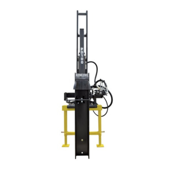
Table of Contents Specifications PD100 Post Driver Specifications/Requirements Dimensions Introduction 130” Height (Extended) 100” Height (Locked Position) Equipment Inspection and Storage Width 33” 20” Depth Warning Labels Weight 460 lbs. Dimension & weight do not include Assembly/Disassembly mounting Short Channel... -
Page 3: Introduction
If parts are missing manufacture or sale at any time, without notice or if damage has been found contact Kencove and without any liability or other obligation on Farm Fence Supplies promptly. - Page 4 7. Debris Guard Inspect complete hydraulic 8. Post Holder Assembly system for leaks or signs of Kencove Farm Fence Supplies recommends wear. Place debris guard in correct for best life and service of this equipment that it is always stored in a clean, dry, and secure position and check that it is in location.
-
Page 5: Assembly/Disassembly
Assembly/ Disassembly NOTE: These are recommended positions and can vary depending on type and make of power supply equipment. Top position – Is used to mount to the front of a tractor. Middle position – Three-point hitch mounting. Lower position – this position will permit the driving of 10 foot tall posts. -
Page 6: 3-Point Hitch Mount/Stabilizer
KD-3 KD-5 Manual Tilt Base Plate Assembly 1. Place the base plate centered on three- point hitch mount with the top crank handle above the stabilizer legs. 2. Using the four (4) 5/8-11 x 2” bolts, 5/8 washers, 5/8 lock washers, and 5/8- 11 nuts, mount base plate on the three- point hitch and securely tighten. - Page 7 2. Locate two (2) mounting pins and four Removing Base Plate/Hitch from Ram (4) cotter pins. WARNING! Before removing the NOTE: A floor jack may be used to assist in base plate/hitch, the ram assembly stabilizing Base Plate /Hitch mounting and must be secured to an adequate object to aligning mounting holes.
-
Page 8: Hydraulic System
KD-9 Hydraulic Hoses and Adapter Kit 1. Supply Line – 1/2"(12MM) X 8FT. 2. Return Line – 1”(25MM) X 8FT. 3. Cylinder Line - 3/4" (19MM) X 3FT. 4. Fitting – 1/2" X 90 DEG. (O-RING) 5. Fitting – 3/4" X 45 DEG. (O-RING) 6. -
Page 9: Hydraulic Hoses
3. Remove three (3) plastic plugs from valve. IMPORTANT! Hydraulic system fittings are o-ring sealed. Do not use paste or tape- type sealer, this can damage o-ring seals and voids warranty of all parts of the hydraulic system. KD-13 Connect Hydraulic Hoses (Post Driver) 1. -
Page 10: Debris Guard
Serious injury, death, and/or property damage may be a result from not securing unit. 1-800-536-2683 WWW.KENCOVE .COM REV.1.10.13... - Page 11 KD-15 KD-17 1. Mount post holder mounting bracket to Post Holder Assembly short channel assembly using two (2) 3/4-10 X 2” bolts, 3/4 lock washers, 1. Assemble post holder by bolting post and 3/4-10 nuts, securely tighten. guide to arm as shown above. Use one (Bolts need to be installed so that the (1) 5/8-11 X 2-1/4”...
- Page 12 Ram I-beam and swing back to the arm stop on the KD-22 mount bracket. NOTE: Your Kencove Post Driver Ram Assembly comes pre-assembled from the warehouse. The following instructions are for service and maintenance. REV.1.10.13...
-
Page 13: Ram Assembly
Ram Disassembly 13. Remove guide blocks and shims from ram I-beam. 1. Remove lynch pin from road lock pin and remove pin. Ram Assembly 2. Slide the main carriage channel toward 1. Place Ram I-beam Assembly top of unit as far as possible; this will horizontal with the cylinder mounting take the tension off the springs. - Page 14 5. The main carriage channel should slide NOTE: Hydraulic ram cylinder must be back and forth in the ram I-beam placed in main carriage channel before springs freely. can be inserted. Center the cylinder loose in 6. Check the side to side movement of the the ram beam.
- Page 15 KD-28 KD-27 15. Align spring and install onto two (2) road lock bracket bolts. 16. Align and install ram cylinder mounting bracket onto two (2) road lock bracket bolts. 17. Install two (2) 3/8-16 locknuts onto bolts. Do not tighten at this time. 18.
-
Page 16: Ram Cylinder
23. Attach ram cylinder rod to the top of Ram Cylinder Seal Disassembly the ram I-beam using new lock washer and new lock nut. (Never reuse locknuts) Securely tighten the nut. Do not over tighten locknut. Ram Cylinder Disassembly KD-31 1 O-Ring Seal 1 O-ring Washer 1 Shaft Wiper... -
Page 17: Safety
Ram Cylinder Assembly 4. Do not modify the hydraulic lever control valve or remove safety neutral 1. Replace piston guide onto shaft and bracket. secure into place with new locking nut. 5. Be aware of underground utilities. If 2. Slide shaft into open end of cylinder unsure of locations, call your local body taking caution not to contact the utility companies. -
Page 18: Operating Instructions
Operating Instructions 5. Remove securing device from Post Driver. 6. Road lock pin is to be secure in top position for storage. Before WARNING! Personal protective transporting more than one-hundred equipment should be worn during (100) feet, raise ram and reposition all procedures. -
Page 19: Drive A Post
6. Release all pressure from the Post WARNING! IT IS IMPORTANT Driver hydraulic system. Disconnect THAT ALL SAFETY STEPS the Driver’s 1/2” hydraulic pressure MENTIONED BELOW BE FOLLOWED. hose to the equipment’s hydraulic FAILURE TO FOLLOW THESE supply (pressure side). Disconnect the INSTRUCTIONS OR CONFORM TO Driver’s 3/4”... - Page 20 9. Swing post holder assembly so that the guides contact and secure post. 10. The Post Driver operator is to never stand directly in front of equipment. Stand to the valve side of equipment. 1-800-536-2683 WWW.KENCOVE .COM REV.1.10.13...
-
Page 21: Service
Service SUB-ASSEMBLY PARTS Kencove post driver PD-100 manual tilt unit is designed for easy maintenance with only six 3-POINT HITCH MOUNTING BRACKET (6) moving parts, and only takes just a few minutes to mount or detach. Take the follow precautions before serving post driver: ... -
Page 22: Ram Assembly
RAM ASSEMBLY KD-35 1 Ram I-Beam 1 Road Lock Pin 1 Main Channel Assembly 1 Lynch Pin 4 Rubber Stop w/nuts and washers 4 Nyrim Guide Blocks 2 1/4-20 X 1-1/4 Hex Bolts 2 10 Gauge Shims 2 1/4 Lock Washers 2 14 Gauge Shims 1 Debris Guard 2 18 Gauge Shims... -
Page 23: Manual Tilt Base Plate
MANUAL TILT BASE PLATE KD-36 1 Valve Assembly 1 Screw Block Plate 2 5/16-18 X 3” Hex Bolts 1 Screw Block w/bolt 2 5-16 Lock Washers 1 Side to Side Crank 2 5/16-18 Hex Nuts 1 3/4-10 Lock Nuts 1 Base Plate Assembly 1 Crank Collar 1 Short Channel Assembly 1 Forward Tilt Yoke... -
Page 24: Troubleshooting
Ram Assembly centered and parallel with Ram Assembly Main Channel or Ram I-beam is Do Not attempt to operate damaged and contact Kencove Farm Fence Supplies for replacement parts Low power or limited Insufficient hydraulic pressure from Verify power supply is... -
Page 25: Warranty
This warranty covers There is no obligation or liability of any kind defects in materials and workmanship to the by Kencove Farm Fence Supplies on account Post Driver. of any of its equipment and shall not be liable for special or consequential damages unless stated in this warranty.
Need help?
Do you have a question about the PD100 and is the answer not in the manual?
Questions and answers