Table of Contents
Advertisement
Available languages
Available languages
Quick Links
Advertisement
Table of Contents

Related Manuals for Conrad 970A SLI Krait Edition


Summary of Contents for Conrad 970A SLI Krait Edition
- Page 1 Preface 970A SLI Krait Edition Motherboard G52-76931XN...
- Page 2 Copyright Notice The material in this document is the intellectual property of MICRO-STAR INTERNATIONAL. We take every care in the preparation of this document, but no guarantee is given as to the correctness of its contents. Our products are under continual improvement and we reserve the right to make changes without notice.
- Page 3 Smartphone Application is a smart web gadget that works as a shopping navigator and provides specs comparison for IT buyers. With a simple tap of the smartphone, you'll efficiently locate your ideal products from a wide variety of choices and, if product details are required, you may easily download user manuals within minutes.
- Page 4 Safety Instructions ■ Always read the safety instructions carefully. ■ Keep this User’s Manual for future reference. ■ Keep this equipment away from humidity. ■ Lay this equipment on a reliable flat surface before setting it up. ■ The openings on the enclosure are for air convection hence protects the equipment from overheating.
- Page 5 FCC-B Radio Frequency Interference Statement This equipment has been tested and found to comply with the limits for a Class B digital device, pursuant to Part 15 of the FCC Rules. These limits are designed to provide reasonable protection against harmful interference in a residential installation. This equipment generates, uses and can radiate radio frequency energy and, if not installed and used in accordance with the instructions, may cause harmful interference to radio communications.
- Page 6 Radiation Exposure Statement This equipment complies with FCC radiation exposure limits set forth for an uncontrolled environment. This equipment and its antenna should be installed and operated with minimum distance 20 cm between the radiator and your body. This equipment and its antenna must not be co-located or operating in conjunction with any other antenna or transmitter.
- Page 7 Battery Information European Union: Batteries, battery packs, and accumulators should not be disposed of as unsorted household waste. Please use the public collection system to return, recycle, or treat them in compliance with the local regulations. Taiwan: For better environmental protection, waste batteries should be collected separately for recycling or special disposal.
- Page 8 WEEE (Waste Electrical and Electronic Equipment) Statement ENGLISH To protect the global environment and as an environmentalist, MSI must remind you that... Under the European Union (“EU”) Directive on Waste Electrical and Electronic Equipment, Directive 2002/96/EC, which takes effect on August 13, 2005, products of “electrical and electronic equipment”...
- Page 9 ESPAÑOL MSI como empresa comprometida con la protección del medio ambiente, recomienda: Bajo la directiva 2002/96/EC de la Unión Europea en materia de desechos y/o equipos electrónicos, con fecha de rigor desde el 13 de agosto de 2005, los productos clasificados como “eléctricos y equipos electrónicos”...
- Page 10 TÜRKÇE Çevreci özelliğiyle bilinen MSI dünyada çevreyi korumak için hatırlatır: Avrupa Birliği (AB) Kararnamesi Elektrik ve Elektronik Malzeme Atığı, 2002/96/EC Kararnamesi altında 13 Ağustos 2005 tarihinden itibaren geçerli olmak üzere, elektrikli ve elektronik malzemeler diğer atıklar gibi çöpe atılamayacak ve bu elektonik cihazların üreticileri, cihazların kullanım süreleri bittikten sonra ürünleri geri toplamakla yükümlü...
- Page 11 日本JIS C 0950材質宣言 日本工業規格JIS C 0950により、2006年7月1日以降に販売される特定分野の電気お よび電子機器について、製造者による含有物質の表示が義務付けられます。 http://www.msi.com/html/popup/csr/cemm_jp.html http://tw.msi.com/html/popup/csr_tw/cemm_jp.html India RoHS This product complies with the “India E-waste (Management and Handling) Rule 2011” and prohibits use of lead, mercury, hexavalent chromium, polybrominated biphenyls or polybrominated diphenyl ethers in concentrations exceeding 0.1 weight % and 0.01 weight % for cadmium, except for the exemptions set in Schedule 2 of the Rule.
-
Page 12: Table Of Contents
CONTENTS ▍ English ...................... En-1 Motherboard Specifications ................En-2 Connectors Quick Guide ..................En-5 Back Panel Quick Guide ..................En-7 CPU (Central Processing Unit) ................En-8 Memory ......................En-11 Mounting Screw Holes ..................En-12 Power Supply ....................En-13 Expansion Slots ....................En-14 Video/ Graphics Cards ..................En-15 Internal Connectors ..................En-16 Jumper ......................En-22 Drivers and Utilities ..................En-23 BIOS Setup ......................En-24... - Page 13 Cartes Vidéo/ Graphics ..................Fr-15 Connecteurs internes ..................Fr-16 Cavaliers ......................Fr-22 Pilotes et Utilitaires ....................Fr-23 Configuration BIOS ...................Fr-24 Русский ....................Ru-1 Характеристики материнской платы .............. Ru-2 Краткое руководство по разъемам ..............Ru-5 Краткое руководство по работе с задней панелью ........Ru-7 ЦП (центральный процессор) ................. Ru-8 Память...
-
Page 15: English
English Thank you for choosing the 970A SLI Krait Edition Series (MS-7693 v5.X) ATX motherboard. The 970A SLI Krait Edition Series motherboards are based on AMD 970 & SB950 chipset for optimal system efficiency. Designed ® to fit the advanced AMD AM3/ AM3+ processor, the 970A SLI Krait Edition ®... -
Page 16: Motherboard Specifications
Motherboard Specifications CPU Support ■ Supports AMD / Phenom II/ Athlon II and Sempron ® processors for the AM3/ AM3+ socket Hypertransport ■ HyperTransport™ 3.0, supports up to 4.8 GT/s Chipset ■ AMD 970 & SB950 ® Memory ■ 4x DDR3 memory slots supporting up to 32GB ■... - Page 17 Internal ■ 1x 24-pin ATX main power connector ■ 1x 8-pin ATX 12V power connector Connectors ■ 6x SATA 6Gb/s connectors ■ 3x USB 2.0 connectors (supports additional 6 USB 2.0 ports) ■ 1x USB 3.0 connector (supports additional 2 USB 3.0 ports) ■...
- Page 18 Software ■ Drivers ■ MSI - Command Center - Live Update 6 - Fast Boot ■ 7-ZIP ■ Norton Internet Security Solution Form Factor ■ ATX Form Factor ■ 12 in. x 8.9 in. (30.5 cm x 22.4 cm) For the latest information about CPU, please visit http://www.msi.com/cpu-support/ For more information on compatible components, please visit http://www.msi.com/test-report/...
-
Page 19: Connectors Quick Guide
Connectors Quick Guide DIMM4 JPWR2 DIMM3 DIMM2 DIMM1 SYSFAN2 CPUFAN CPU Socket Back Panel JPWR1 PCI_E1 SYSFAN1 PCI_E2 SATA1 SATA2 PCI_E3 JCI1 SATA5_6 PCI1 SATA3_4 PCI_E4 JBAT1 JFP2 PCI2 JUSB4 JFP1 JAUD1 JCOM1 JUSB3 JUSB2 JTPM1 JUSB1 En-5... - Page 20 Connectors Reference Guide Port Name Port Type Page AM3/ AM3+ Socket En-8 CPUFAN,SYSFAN1~2 Fan Power Connectors En-17 DIMM1~4 DDR3 Memory slots En-11 JAUD1 Front Panel Audio Connector En-21 JBAT1 Clear CMOS Jumper En-22 JCI1 Chassis Intrusion Connector En-20 JCOM1 Serial Port Connector En-21 JFP1, JFP2 System Panel Connectors...
-
Page 21: Back Panel Quick Guide
Back Panel Quick Guide LAN Port PS/2 Mouse Port Line-In RS-Out USB 2.0 Port USB 2.0 Port USB 3.1 Port Line-Out CS-Out PS/2 Keyboard USB 2.0 Port SS-Out Port ▶ PS/2 Mouse/ Keyboard Port The PS/2 mouse/ keyboard DIN connectors are for PS/2 mouse/ keyboard. -
Page 22: Cpu (Central Processing Unit
CPU (Central Processing Unit) Introduction to AM3/ AM3+ CPU The surface of the CPU has a golden triangle to assist in correctly lining up the CPU for motherboard placement. The golden triangle is the Pin 1 indicator. Golden triangle is the Pin 1 indicator Important Overheating Overheating can seriously damage the CPU and motherboard. - Page 23 CPU & Cooler Installation When you are installing the CPU, make sure the CPU has a cooler attached on the top to prevent overheating. Meanwhile, do not forget to apply some thermal paste on CPU before installing the heat sink/cooler fan for better heat dispersion. Follow the steps below to install the CPU &...
- Page 24 5. Locate the CPU fan connector on the motherboard. 6. Position the cooling set onto the retention mechanism. Hook one end of the clip to hook first. CPU fan connector 7. Then press down the other end of the clip to fasten the cooling set on the top of the retention mechanism.
-
Page 25: Memory
Memory These DIMM slots are used for installing memory modules. DIMM1 DIMM2 DIMM3 DIMM4 Video Demonstration Watch the video to learn how to install memories. http://youtu.be/76yLtJaKlCQ Dual-Channel mode Population Rule In Dual-Channel mode, the memory modules can transmit and receive data with two data bus channels simultaneously. -
Page 26: Mounting Screw Holes
Mounting Screw Holes When installing the motherboard, first install the necessary mounting stands required for an motherboard on the mounting plate in your computer case. If there is an I/O back plate that came with the computer case, please replace it with the I/O backplate that came with the motherboard package. -
Page 27: Power Supply
Power Supply Video Demonstration Watch the video to learn how to install power supply connectors. http://youtu.be/gkDYyR_83I4 JPWR1~2: ATX Power Connectors These connectors allow you to connect an ATX power supply. To connect the ATX power supply, align the power supply cable with the connector and firmly press the cable into the connector. -
Page 28: Expansion Slots
Expansion Slots This motherboard contains numerous slots for expansion cards, such as discrete graphics or audio cards. PCI_E1~4: PCIe Expansion Slots The PCIe slot supports the PCIe interface expansion card. PCIe x16 Slot PCIe x1 Slot PCI1~2: PCI Expansion Slots The PCI slot supports additional LAN, SCSI, USB, and other add-on cards that comply with PCI specifications. -
Page 29: Video/ Graphics Cards
Video/ Graphics Cards If available, this motherboard takes advantage of the CPU’s integrate graphics processor, but discrete video cards can be installed by way of the motherboard’s expansion slots. Adding on one or more discrete video cards will significantly boost the system’s graphics performance. -
Page 30: Internal Connectors
Internal Connectors SATA1~6: SATA Connectors This connector is a high-speed SATA interface port. Each connector can connect to one SATA device. SATA devices include disk drives (HDD), solid state drives (SSD), and optical drives (CD/ DVD/ Blu-Ray). Video Demonstration Watch the video to learn how to Install SATA HDD. http://youtu.be/RZsMpqxythc SATA1 SATA2... - Page 31 CPUFAN,SYSFAN1~2: Fan Power Connectors The fan power connectors support system cooling fans with +12V. If the motherboard has a System Hardware Monitor chipset on-board, you must use a specially designed fan with a speed sensor to take advantage of the CPU fan control. Remember to connect all system fans.
- Page 32 JFP1, JFP2: System Panel Connectors These connectors connect to the front panel switches and LEDs. When installing the front panel connectors, please use the optional M-Connector to simplify installation. Plug all the wires from the computer case into the M-Connector and then plug the M-Connector into the motherboard.
- Page 33 JUSB1~3: USB 2.0 Expansion Connectors This connector is designed for connecting high-speed USB peripherals such as USB HDDs, digital cameras, MP3 players, printers, modems, and many others. Important Note that the VCC and GND pins must be connected correctly to avoid possible damage.
- Page 34 JCI1: Chassis Intrusion Connector This connector connects to the chassis intrusion switch cable. If the computer case is opened, the chassis intrusion mechanism will be activated. The system will record this intrusion and a warning message will flash on screen. To clear the warning, you must enter the BIOS utility and clear the record.
- Page 35 JCOM1: Serial Port Connector This connector is a 16550A high speed communication port that sends/receives 16 bytes FIFOs. You can attach a serial device. JAUD1: Front Panel Audio Connector This connector allows you to connect the front audio panel located on your computer case.
-
Page 36: Jumper
Jumper JBAT1: Clear CMOS Jumper There is CMOS RAM onboard that is external powered from a battery located on the motherboard to save system configuration data. With the CMOS RAM, the system can automatically boot into the operating system (OS) every time it is turned on. If you want to clear the system configuration, set the jumpers to clear the CMOS RAM. -
Page 37: Drivers And Utilities
Drivers and Utilities After you install the operating system you will need to install drivers to maximize the performance of the new computer you just built. MSI motherboard comes with a Driver Disc. Drivers allow the computer to utilize your motherboard more efficiently and take advantage of any special features we provide. -
Page 38: Bios Setup
BIOS Setup CLICK BIOS is developed by MSI that provides a graphical user interface for setting parameters of BIOS by using the mouse and the keybord. With the CLICK BIOS, users can change BIOS settings, monitor CPU temperature, select the boot device priority and view system information such as the CPU name, DRAM capacity, the OS version and the BIOS version. - Page 39 Overview After entering BIOS, the following screen is displayed. Temperature monitor Language System information Boot device priority bar Virtual OC Genie Button BIOS menu BIOS menu selection selection Menu display ▶ BIOS menu selection The following options are available: ■ SETTINGS - Uses this menu to specify the parameters for chipset and boot devices.
- Page 40 ▶ Virtual OC Genie Button Enables or disables the OC Genie function by clicking on this button. When enabled, this button will be light. Enabling OC Genie function can automatically overclock with MSI optimized overclocking profile. Important We recommend that you do not to make any modification in OC menu mode and do not to load defaults after enabling the OC Genie function.
- Page 41 Operation You can control BIOS settings with the mouse and the keyboard. The following table lists and describes the hot keys and the mouse operations. Hot key Mouse Description <↑↓→← > Select Item Move the cursor <Enter> Select Icon/ Field Click/ Double-click the left button...
- Page 42 OC Menu This menu is for advanced users who want to overclock the mainboard. Important • Overclocking your PC manually is only recommended for advanced users. • Overclocking is not guaranteed, and if done improperly, can void your warranty or severely damage your hardware.
- Page 43 ▶ Adjusted CPU-NB Frequency Shows the adjusted CPU frequency. Read-only. ▶ CPU Smart Protection CPU Smart Protection is a mechanism of CPU overheating protection. It will automati- cally reduce the clock when the CPU temperature gets too high. ▶ CPU Core Control This item allows you to select the number of active processor cores.
- Page 44 ▶ Adjust PCI-E Frequency (MHz) Sets the PCI Express frequency. ▶ Unlock CPU Core [Disabled] This item is used to unlock the CPU core. Please refer to the procedures below for CPU core unlocked in BIOS setup. Enter “OC” and set “Unlock CPU Core” to [Enabled]. Set “Adjust CPU-NB Ratio”...
- Page 45 Important • If you do not have any EMI problem, leave the setting at [Disabled] for optimal system stability and performance. But if you are plagued by EMI, select the value of Spread Spectrum for EMI reduction. • The greater the Spread Spectrum value is, the greater the EMI is reduced, and the system will become less stable.
- Page 46 ▶ SVM Mode [Enabled] Enables or disables CPU Virtualization. [Enabled] Enables CPU Virtualization and allows a platform to run multiple operating systems in independent partitions. The system can function as multiple systems virtually. [Disabled] Disables this function. ▶ IOMMU Mode Enables/disables the IOMMU (I/O Memory Management Unit) for I/O Virtualization.
-
Page 47: Deutsch
Deutsch Danke, dass Sie sich für das 970A SLI Krait Edition (MS-7693 v5.X) ATX Motherboard gewählt haben. Das 970A SLI Krait Edition Motherboard basiert auf dem AMD 970 & SB950 Chipsatz und ermöglicht so ein optimales und ® effizientes System. Entworfen, um den hochentwickelten AMD AM3/ AM3+ ®... -
Page 48: Spezifikationen
Spezifikationen Prozessor ■ Unterstützt AMD / Phenom II/ Athlon II und Sempron ® Prozessoren für AM3/ AM3+ Sockel Hypertransport ■ HyperTransport™ 3.0, unterstützt bis zu 4,8 GT/s Chipsatz ■ AMD 970 & SB950 ® Speicher ■ 4x DDR3 Speicherplätze unterstützen bis zu 32GB ■... - Page 49 Interne ■ ATX 24-poliger Stromanschluss x1 ■ ATX12V 8-poliger Stromanschluss x1 Anschlüsse ■ SATA 6Gb/s Anschlüsse x6 ■ USB 2.0 Anschlüsse x3 (unterstützt zusätzliche 6 USB 2.0 Ports) ■ USB 3.0 Anschluss x1 (unterstützt zusätzliche 2 USB 3.0 Ports) ■ 4-poliger CPU-Lüfter-Anschluss x1 ■...
- Page 50 Software ■ Treiber ■ MSI - Kommandozentrale - Live Update 6 - Fast Boot ■ 7-ZIP ■ Norton Internet Security Solution Formfaktor ■ ATX Formfaktor ■ 12 Zoll x 8,9 Zoll (30,5 cm x 22,4 cm) Weitere CPU Informationen finden Sie unter http://www.msi.com/cpu-support/ Die neusten Informationen über kompatible Bauteile finden Sie unter http://www.msi.com/test-report/...
-
Page 51: Anschlussübersicht
Anschlussübersicht DIMM4 JPWR2 DIMM3 DIMM2 DIMM1 SYSFAN2 CPUFAN CPU Sockel Rücktafel JPWR1 PCI_E1 SYSFAN1 PCI_E2 SATA1 SATA2 PCI_E3 JCI1 SATA5_6 PCI1 SATA3_4 PCI_E4 JBAT1 JFP2 PCI2 JUSB4 JFP1 JAUD1 JCOM1 JUSB3 JUSB2 JTPM1 JUSB1 De-5... - Page 52 Übersicht der Motherboard-Anschlüsse Port-Name Port-Typ Seite AM3/ AM3+ Sockel De-8 CPUFAN,SYSFAN1~2 Stromanschlüsse für Lüfter De-17 DIMM1~4 DDR3 Speichersteckplätze De-11 JAUD1 Audioanschluss des Frontpanels De-21 JBAT1 Steckbrücke zur CMOS-Löschung De-22 JCI1 Gehäusekontaktanschluss De-20 JCOM1 Serieller Anschluss De-21 JFP1, JFP2 Systemtafelanschlüsse De-18 JPWR1~2 ATX Stromanschlüsse De-13...
-
Page 53: Rücktafel-Übersicht
Rücktafel-Übersicht PS/2 Maus- LAN Anschluss anschluss USB 2.0 USB 2.0 USB 3.1 Line-In RS-Out Anschluss Anschluss Anschluss Line-Out CS-Out PS/2 Tastatur- USB 2.0 SS-Out anschluss Anschluss ▶ PS/2 Maus-/ Tastaturanschluss Die PS/2 Maus/Tastatur Stecker DIN ist für eine PS/2 Maus/Tastatur. ®... -
Page 54: Cpu (Prozessor
CPU (Prozessor) Erklärung zur AM3/ AM3+ CPU Die Obserseite der CPU hat ein gelbes Dreieck um die korrekte Ausrichtung der CPU auf dem Motherboard zu gewährleisten. Das gelbe Dreieck des Prozessors definiert die Position des ersten Pins. Das goldene Dreieck des Prozessors definiert die Position des ersten Pins Wichtig Überhitzung... - Page 55 CPU & Kühler Einbau Wenn Sie die CPU einbauen, stellen Sie bitte sicher, dass Sie auf der CPU einen Kühler anbringen, um Überhitzung zu vermeiden. Vergessen Sie nicht, etwas Siliziumwärmeleitpaste auf die CPU aufzutragen, bevor Sie den Prozessorkühler installieren, um eine Ableitung der Hitze zu erzielen. Folgen Sie den Schritten unten, um die CPU und den Kühler ordnungsgemäß...
- Page 56 5. Machen Sie den CPU-Lüfteranschluss auf dem Motherboard ausfinding. 6. Setzen Sie den Kühler auf die Kühlerhalterung und hacken Sie zuerst ein Ende des Kühlers an dem Modul fest. CPU-Lüfteranschluss 7. Dann drücken Sie das andere Ende des Bügels herunter, um den Kühler auf der Kühlerhalterung zu fixieren .
-
Page 57: Speicher
Speicher Diese DIMM-Steckplätze nehmen Arbeitsspeichermodule auf. DIMM1 DIMM2 DIMM3 DIMM4 Video-Demonstration Anhand dieses Video an untenstehender Adresse erfahren Sie, wie Sie die Speichermodule installieren. http://youtu.be/76yLtJaKlCQ Populationsregeln für Dual-Kanal-Speicher Im Dual-Kanal-Modus können Arbeitsspeichermodule Daten über zwei Datenbusleitungen gleichzeitig senden und empfangen. Durch Aktivierung des Dual- Kanal-Modus wird die Leistung Ihres Systems verbessert. -
Page 58: Schraubenlöcher Für Die Montage
Schraubenlöcher für die Montage Verwenden Sie die dem Motherboard beiliegende I/O-Platte und setzen Sie sie mit leichtem Druck von innen in die Aussparung des Computergehäuses ein. Zur Installation des Motherboards in Ihrem PC-Gehäuse befestigen Sie zunächst die dem Gehäuse beiliegenden Abstandhalter im Gehäuse. Legen Sie das Motherboard mit den Schraubenöffnungen über den Abstandhaltern und schrauben Sie das Motherboard mit den dem Gehäuse beiliegenden Schrauben fest. -
Page 59: Stromversorgung
Stromversorgung Video-Demonstration Anhand dieses Video an untenstehender Adresse erfahren Sie, wie Sie die Stromversorgungsstecker installieren. http://youtu.be/gkDYyR_83I4 JPWR1~2: ATX Stromanschlüsse Mit diesem Anschluss verbinden Sie den ATX Stromanschlusse. Achten Sie bei dem Verbinden des ATX Stromanschlusses darauf, dass der Anschluss des Netzteils richtig auf den Anschluss an der Hauptplatine ausgerichtet ist. -
Page 60: Erweiterungssteckplätze
Erweiterungssteckplätze Dieses Motherboard enthält zahlreiche Schnittstellen für Erweiterungskarten, wie diskrete Grafik-oder Soundkarten. PCI_E1~4: PCIe Erweiterungssteckplätze Der PCIe Steckplatz unterstützt PCIe-Erweiterungskarten. PCIe x16-Steckplatz PCIe x1-Steckplatz PCI1~2: PCI Erweiterungssteckplätze Der PCI-Steckplatz kann LAN-Karten, SCSI-Karten, USB-Karten und sonstige Zusatzkarten aufnehmen, die mit den PCI-Spezifikationen konform sind. PCI-Steckplatz Wichtig Achten Sie darauf, dass Sie den Strom abschalten und das Netzkabel aus der... -
Page 61: Video/ Grafikkarten
Video/ Grafikkarten Fall im Prozessor integriert, nutzt dieses Motherboard den im Prozessor befindlichen Grafikprozessor. Zusätzliche Grafikkarten können aber über die auf dem Motherboard verfügbaren Erweiterungssteckplätze eingesetzt werden um die Systemleistung zu erhöhen. Video-Demonstration Anhand dieses Video an untenstehender Adresse erfahren Sie, wie Sie eine Grafikkarte im PCIe x16 Steckplatz mit Butterfly-Verschlüssen installieren. -
Page 62: Interne Anschlüsse
Interne Anschlüsse SATA1~6: SATA Anschlüsse Dieser Anschluss basiert auf der Hochgeschwindigkeitsschnittstelle Serial ATA (SATA). Pro Anschluss kann ein Serial ATA Gerät angeschlossen werden. Zu Serial ATA Geräten gehören Festplatten (HDD), SSD Festplatten (SSD) und optische Laufwerke (CD-/DVD-/Blu-Ray-Laufwerke). Video-Demonstration Anhand dieses Video an untenstehender Adresse erfahren Sie, wie Sie eine SATA-Featplatte installieren. - Page 63 CPUFAN,SYSFAN1~2: Stromanschlüsse für Lüfter Die Anschlüsse unterstützen aktive Systemlüfter mit +12V. Ist Ihr Motherboard mit einem Chipsatz zur Überwachung der Systemhardware versehen, dann brauchen Sie einen speziellen Lüfter mit Geschwindigkeitsregelung, um die Vorteile der Steuerung des CPU Lüfters zu nutzen. Vergessen Sie nicht, alle Systemlüftern anzuschließen. Einige Systemlüfter können nicht direkt an dem Motherboard angeschlossen werden und müssen stattdessen mit dem Netzteil direkt verbunden werden.
- Page 64 JFP1, JFP2: Systemtafelanschlüsse Diese Anschlüsse sind für das Frontpanel angelegt. Sie dienen zum Anschluss der Schalter und LEDs des Frontpanels. Bei der Installation des Frontpanel-Anschlüsse, nutzen Sie bitte die optionalen M-Connectors um die Installation zu vereinfachen. Schließen Sie alle Kabel aus dem PC-Gehäuse zunächst an die M-Connectors an und stecken Sie die M-Connectors auf das Motherboard.
- Page 65 JUSB1~3: USB 2.0 Erweiterungsanschlüsse Dieser Anschluss eignet sich für die Verbindung der Hochgeschwindigkeits- USB- Peripheriegeräte, wie z.B. USB Festplattenlaufwerke, Digitalkameras, MP3-Player, Drucker, Modems und ähnliches. Wichtig Bitte beachten Sie, dass Sie die mit VCC (Stromführende Leitung) und GND (Erdleitung) bezeichneten Pins korrekt verbinden müssen, ansonsten kann es zu Schäden kommen.
- Page 66 JCI1: Gehäusekontaktanschluss Dieser Anschluss wird mit einem Kontaktschalter verbunden. Wenn das PC-Gehäuse geöffnet wird, aktiviert dies den Gehäuse-Kontaktschalter und eine Warnmeldung wird auf dem Bildschirm angezeigt. Um die Warnmeldung zu löschen, muss das BIOS aufgerufen und die Aufzeichnung gelöscht werden. JTPM1: TPM Anschluss Dieser Anschluss wird für das TPM Modul (Trusted Platform Module) verwendet.
- Page 67 JCOM1: Serieller Anschluss Es handelt sich um eine 16550A Kommunikationsschnittstelle, die 16 Bytes FIFOs sendet/empfängt. Hier lässt sich eine serielle Maus oder andere serielle Geräte direkt anschließen. JAUD1: Audioanschluss des Frontpanels Dieser Anschluss ermöglicht den Anschluss von Audio Ein- und Ausgängen eines Frontpanels.
-
Page 68: Steckbrücke
Steckbrücke JBAT1: Steckbrücke zur CMOS-Löschung Der Onboard CMOS Speicher (RAM) wird durch eine externe Spannungsversorgung durch eine Batterie auf dem Motherboard versorgt, um die Daten der Systemkonfiguration zu speichern. Er ermöglicht es dem Betriebssystem, mit jedem Einschalten automatisch hochzufahren. Wenn Sie die Systemkonfiguration löschen wollen, müssen Sie die Steckbrücke für kurze Zeit umsetzen. -
Page 69: Treiber Und Dienstprogramme
Treiber und Dienstprogramme Nach der Installation des Betriebssystems müssen Sie Treiber installieren, um die Leistung des neuen Computers zu maximieren. Dem MSI Mainbaord liegt eine Treiber-CD bei. Die enthaltenen Treiber ermöglichen es Ihnen, das Motherboard effizienter zu nutzen und von den besonderen Eigenschaften des MSI Motherboards zu profitieren. -
Page 70: Bios Setup
BIOS Setup CLICK BIOS wurde von MSI entwickelt, es bietet eine intuitiv bedienbare grafische Benutzeroberfläche in der BIOS-Parameter einfach per Maus und Tastatur konfiguriert werden können. Mit CLICK BIOS können Benutzer alle wichtigen BIOS-Einstellungen ändern, die CPU-Temperatur überwachen, die Boot-Reihenfolge festlegen und die Systeminformationen anzeigen, wie CPU-Name, DRAM Kapazität, OS-Version und BIOS-Version. - Page 71 Überbilck Nach dem Aufrufen des BIOS, sehen Sie die folgende Anzeige. Temperaturüberwachung Sprache System- Information Bootgeräte- Prioritäts Virtual OC -leiste Genie Taste BIOS-Menü- BIOS-Menü- Auswahl Auswahl Menüanzeige ▶ BIOS-Menü-Auswahl Die folgenden Optionen stehen zur Verfügung: ■ SETTINGS - Mit diesem Menü können Sie die Parameter für Chipsatz, Boot- Geräte angeben.
- Page 72 ▶ Virtual OC Genie Taste Aktivieren oder deaktivieren Sie die OC Genie Funktion durch einen Klick auf diese Taste. Wenn aktiviert, leuchtet diese Taste auf. Aktivieren Sie die OC Genie-Funktion mit einem von MSI optimierten Übertaktungsprofil automatisch zu übertakten. Wichtig Es wird empfohlen, keine Änderung im OC-Menü...
- Page 73 Betrieb Sie können die BIOS-Einstellungen mit der Maus oder der Tastatur steuern. Die folgende Tabelle zeigt und beschreibt die Hotkeys und Mausaktionen. Hotkey Maus Beschreibung <↑↓→← > Auswahl eines Eintrages Bewegen Cursor <Enter> Auswahl eines Symbols/ Feldes Klicken/ doppelt-klick- en Sie mit der linken Maustaste <Esc>...
- Page 74 OC-Menü In diesem Menü können Benutzer das BIOS anpassen und übertakten. Bitte führen Sie nur Änderungen durch, wenn Sie sich über das Ergebniss im Klaren sind. Sie sollten Erfahrung beim Übertakten haben, da Sie sonst das Motherboard oder Komponenten des Systems beschädigen können. Wichtig •...
- Page 75 ▶ Adjusted CPU Frequency Es zeigt die eingestellte Frequenz der CPU an. Es handelt sich um eine Anzeige – Änderungen sind nicht möglich. ▶ Adjust CPU-NB Ratio [Auto] Hier können Sie die CPU-NB-Taktmultiplikator (Ratio) angeben. ▶ Adjusted CPU-NB Frequency Zeigt die verstellte Frequenz der CPU-NB. Nur Anzeige – keine Änderung möglich. ▶...
- Page 76 ▶ HT Link Speed Gibt die Betriebsfrequenz des Taktgebers des Hypertransport Links vor. Mit der Einstellung [Auto], erkennt das System die HT Link Geschwindigkeit automatisch. ▶ Adjusted HT Link Frequency Gibt der verstellt Frequenz des HT-Links. Nur Anzeige. ▶ HT Link Control Drücken Sie die Eingabetaste <Enter>, um das Untermenü...
- Page 77 ▶ XXX Voltage [Auto] (optional) Einstellung dieser Spannungen. Wenn die Einstellung auf [Auto] gesetzt ist, wird das BIOS die Spannungen automatisch eingestellt oder Sie können es manuell einstellen. ▶ Spread Spectrum [Disabled] Diese Funktion reduziert die EMI (Electromagnetic Interference) durch Modulation Taktgenerator erzeugten Impulse.
- Page 78 ▶ AMD Cool’n’Quiet [Auto] Aktiviert oder deaktiviert die AMD Cool’n’Quiet Funktion. [Auto] Abhängig von AMD Design-Empfehlung. [Enable] Aktiviert die AMD Cool’n’Quiet Funktion. Die Cool’n’Quiet-Technologie kann die CPU-Geschwindigkeit und den Stromverbrauch effizient und dynamisch herabsetzen. [Disabled] Deaktiviert diese Funktion. Wichtig Wenn die CPU-Ratio Setting setzt, dann Cool’n’Quiet-Funktion automatisch deaktiviert ist.
-
Page 79: Français
Français Merci d’avoir choisi une carte mère ATX de la série 970A SLI Krait Edition (MS-7693 v5.X). La série 970A SLI Krait Edition est basée sur le chipset 970 & SB950 pour une efficacité optimale. Conçue pour fonctionner ® avec les processeurs AMD AM3/ AM3+, les cartes mère de la série 970A... -
Page 80: Spécifications
Spécifications Processeurs ■ Support AMD / Phenom II/ Athlon II et Sempron ® processeurs pour AM3/ AM3+ socket Hypertransport ■ HyperTransport™ 3.0, support jusqu’à 4.8 GT/s Chipset ■ AMD 970 & SB950 ® Mémoire ■ 4x emplacements de mémoire DDR3 supportent jusqu’à 32GB ■... - Page 81 Connecteurs ■ 1x connecteur d’alimentation principal 24-pin ATX ■ 1x connecteur d’alimentation 8-pin ATX 12V internes ■ 6x connecteurs SATA 6Gb/s ■ 3x connecteurs USB 2.0 (support 6 autres ports USB 2.0) ■ 1x connecteur USB 3.0 (support 2 autres ports USB 3.0) ■...
- Page 82 Logiciel ■ Pilotes ■ MSI - Command Center - Live Update 6 - Fast Boot ■ 7-ZIP ■ Norton Internet Security Solution Dimension ■ Dimensions ATX ■ 12 in. x 8.9 in. (30.5 cm x 22.4 cm) Pour plus d’information sur le CPU, veuillez visiter http://www.msi.com/cpu-support/ Pour plus d’information sur les composants compatibles, veuillez visiter...
-
Page 83: Guide Rapide Des Connecteurs
Guide Rapide Des Connecteurs DIMM4 JPWR2 DIMM3 DIMM2 DIMM1 SYSFAN2 CPUFAN CPU Socket Panneau arrière JPWR1 PCI_E1 SYSFAN1 PCI_E2 SATA1 SATA2 PCI_E3 JCI1 SATA5_6 PCI1 SATA3_4 PCI_E4 JBAT1 JFP2 PCI2 JUSB4 JFP1 JAUD1 JCOM1 JUSB3 JUSB2 JTPM1 JUSB1 Fr-5... - Page 84 Guide référence des connecteurs Noms de ports Types des ports Page AM3/ AM3+ Socket Fr-8 CPUFAN,SYSFAN1~2 Connecteurs d'alimentation de ventilateurs Fr-17 DIMM1~4 Emplacements de mémoire DDR3 Fr-11 JAUD1 Connecteur audio avant Fr-21 JBAT1 Cavalier d’effacement CMOS Fr-22 JCI1 Connecteur intrusion châssis Fr-20 JCOM1 Connecteur de port Sérial...
-
Page 85: Guide Rapide Du Panneau Arrière
Guide rapide du panneau arrière Port LAN Port souris PS/2 Ligne-In RS-Out Port USB 2.0 Port USB 2.0 Port USB 3.1 Ligne-Out CS-Out Port clavier PS/2 Port USB 2.0 SS-Out ▶ Port souris/ clavier PS/2 Connecteurs souris/ clavier PS/2 DIN pour une souris ou un clavier PS/2 ®... - Page 86 Processeur : CPU Introduction du AM3/ AM3+ CPU A la surface du CPU, un triangle d'or assiste l'alignement du CPU sur la carte mère. Le triangle d'or est l'indicateur de Pin 1. Le triangle d'or est l'indicateur de Pin 1 Important Surchauffe La surchauffe endommage sérieusement le processeur et le système.
- Page 87 Installation du CPU et son ventilateur Lorsque vous installez le CPU, assurez-vous que le CPU possède un ventilateur attaché sur le haut pour prévenir la surchaffe. En même temps, n'oubliez pas d'appliquer une couche de pâte thermique sur le CPU avant d'installer le ventilateur pour une meilleure dissipation de chaleur.
- Page 88 5. Localisez le connecteur du ventilateur de CPU sur la carte mère. 6. Posez le ventilateur sur le mécanisme de rétention. Crochez un côté du clip d’abord. Connecteur ventilateur CPU 7. Puis appuyez sur l’autre côté du clip pour fixer le ventilateur sur le haut du mécanisme de rétention.
-
Page 89: Mémoire
Mémoire Ces emplacements DIMM sont destinés à installer les modules de mémoire. DIMM1 DIMM2 DIMM3 DIMM4 Démonstration de vidéo Voir le vidéo sur l'installation des mémoires sur le site ci-dessous. http://youtu.be/76yLtJaKlCQ Règle de population en mode double canal En mode de double canal, les modules de mémoire peuvent transmettre et recevoir simultanément deux lignes de données. -
Page 90: Trous Taraudés De Montage
Trous Taraudés de Montage Avant d’installer votre carte mère, il faut d’abord installer les socles de montage néce saires sur le plateau de montage du boîtier de l’ordinateur. Si le boîtier de l’ordinateur est accompagné par un panneau Entrée/ Sortie arrière, veuillez le remplacer et utiliser celui qui est fournit dans la boîte de la carte. -
Page 91: Connecteurs D'alimentation
Connecteurs d’alimentation Démonstration de vidéo Voir le vidéo sur l’installation des connecteurs d’alimentation sur le site ci-dessous. http://youtu.be/gkDYyR_83I4 JPWR1~2 : Connecteur d'alimentation ATX Ce connecteur vous permet de relier une alimentation ATX. Pour cela, alignez le câble d’alimentation avec le connecteur et appuyez fermement le câble dans le connecteur. Si ceci est bien fait, la pince sur le câble d’alimentation doit être accrochée sur le connecteur d’alimentation de la carte mère. -
Page 92: Emplacements D'extension
Emplacements d’extension Cette carte mère contient de nombreux ports pour les cartes d’extension, tels que les cartes graphiques ou les cartes audio. PCI_E1~4 : Emplacements d’extension PCIe L'emplacement PCIe supporte l'interface de carte d'extension PCIe. Emplacement PCIe x16 Emplacement PCIe x1 PCI1~2 : Emplacements d’extension PCI Le slot PCI supporte la carte LAN, la carte SCSI, la carte USB, et d’autre cartes ajoutées qui sont compatibles avec les spécifications de PCI. -
Page 93: Cartes Vidéo/ Graphics
Cartes Vidéo/ Graphics La carte mère peut utiliser la partie graphique intégrée au processeur, mais peut également utiliser une carte vidéo distincte installée sur un port d’extension de la carte mère. Une ou plusieurs cartes vidéo ajoutées peuvent améliorer fortement la performance graphique du système. -
Page 94: Connecteurs Internes
Connecteurs internes SATA1~6 : Connecteurs SATA Ce connecteur est un port d’interface SATA haut débit. Chaque connecteur peut être relié à un appareil SATA. Les appareils SATA sont des disques durs (HDD), disque état solide (SSD), et lecteurs optiques (CD/ DVD/ Blu-Ray). Démonstration de vidéo Voir le vidéo sur l’installation d’un SATA HDD. - Page 95 CPUFAN,SYSFAN1~2 : Connecteur d’alimentation du ventilateur Les connecteurs d’alimentation du ventilateur supportent les ventilateurs de type +12V. Si la carte mère est équipée d’un moniteur du matériel système intégré, vous devrez utiliser un ventilateur spécial pourvu d’un capteur de vitesse afin de contrôler le ventilateur de l’unité...
- Page 96 JFP1, JFP2 : Connecteur panneau système Ces connecteurs se connectent aux interrupteurs et LEDs du panneau avant. Le JFP1 est conforme au guide de conception de la connectivité Entrée/sortie du panneau avant Intel . Lors de l’installation des connecteurs du panneau avant, veuillez utiliser ®...
- Page 97 JUSB1~3 : Connecteurs d’extension USB 2.0 Ce connecteur est destiné à connecter les périphériques USB haute vitesse tels que les disques durs USB, les appareils photo numériques, les lecteurs MP3, les imprimantes, les modems et les appareils similaires. Important Notez que les pins VCC et GND doivent être branchées correctement afin d’éviter tout dommage possible.
- Page 98 JCI1 : Connecteur Intrusion Châssis Ce connecteur est relié à un câble d’interrupteur intrusion châssis. Si le châssis est ouvert, l’interrupteur en informera le système, qui enregistera ce statut et affichera un écran d’alerte. Pour effacer ce message d’alerte, vous devez entrer dans le BIOS et désactiver l’alerte.
- Page 99 JCOM1 : Connecteur de port série Le port de série est un port de communications de haute vitesse de 16550A, qui envoie/ reçoit 16 bytes FIFOs. Vous pouvez attacher un périphérique sérail. JAUD1 : Connecteur audio panneau avant Ce connecteur vous permet de connecter un audio sur le panneau avant.Il est conforme au guide de conception de la connectivité...
-
Page 100: Cavaliers
Cavaliers JBAT1 : Cavalier d’effacement CMOS Il y a un CMOS RAM intégré, qui est alimenté par une batterie externe située sur la carte mère, destiné à conserver les données de configuration du système. Avec le CMOS RAM, le système peut lancer automatiquement le système d’exploitation chaque fois qu’il est allumé. -
Page 101: Pilotes Et Utilitaires
Pilotes et Utilitaires Après l’installation du système d’exploitation, il faut installer des pilotes pour maximiser les performances de l’ordinateur. La carte mère MSI est dotée d’un disque de pilotes. Ces pilotes permettent à l’ordinateur d’employer la carte mère plus efficacement et de bien développer les fonctions fournies. Vous pouvez protéger votre ordinateur des virus par l’installaton des programmes de sécurité... -
Page 102: Configuration Bios
Configuration BIOS CLICK BIOS est développé par MSI qui fournit une interface graphique utilisateur pour régler les paramètres du BIOS a l'aide de la souris et du clavier. Avec CLICK BIOS, vous pouvez modifier les réglages BIOS, surveiller la température du CPU, choisir la priorité... - Page 103 Vue d'ensemble Entrer BIOS, l’écran suivant apparaît. Indicateur température Langue Information du système Barre priorité de périphérique Bouton virtuel démarrage OC Genie Sélection du Sélection du menu BIOS menu BIOS Ecran de menu ▶ Sélection du menu BIOS Les options suivantes sont disponibles : ■...
- Page 104 ▶ Bouton virtuel OC Genie Activer ou désactiver la fonction OC Genie en cliquant sur ce bouton. Lorsqu’il est ac- tivé, le bouton s’allume. Activer la fonction OC Genie peut automatiquement overclock- er avec le profil d’overclocking optimisé MSI. Important Il est conseillé...
- Page 105 Opération Vous pouvez contrôler le réglage BIOS avec la souris et le clavier. La liste ci-dessous décrit les opérations des touches raccourcis et de la souris. Touches Souris Description <↑↓→← > Choisir un article Choisir un champ <Enter> Choisir une icône/ un domaine Cliquer/ Double-cliquer le bouton gauche...
- Page 106 OC Menu Ce menu est destiné aux utilisateur avancés souhaitant overclocker la carte mère. Important • L’Overclocking manuel du PC n’est recommandé que pour les utilisateurs avancés. • L’Overclocking n’est pas garanti, et une mauvaise manipulation peut invalider votre garantie et endommager sévèrement votre matériel. •...
- Page 107 ▶ Adjust CPU-NB Ratio [Auto] Ce menu sert à ajuster le ratio CPU-NB qui sert à déterminer la vitesse CPU-NB. ▶ Adjusted CPU-NB Frequency Il montre la fréquence ajusté du CPU. En lecture seule. ▶ CPU Smart Protection CPU Smart Protection est un mécanisme de la protection d’overclocking du CPU. Il réduit automatiquement la fréquence lorsque la température de CPU est extrêment élevée.
- Page 108 ▶ HT Link Speed Ce menu vous permet de régler la vitesse Hyper-Transport Link. Mis en [Auto], le sys- tème détecte la vitesse HT link automatiquement. ▶ Adjusted HT Link Frequency Il montre la fréquence ajustée HT Link. Lecture uniquement. ▶...
- Page 109 ▶ XXX Voltage [Auto] (en option) Définit les tensions. En "Auto", le BIOS configure ces tension automatiquement. Vous pouvez également les régler manuellement. ▶ Spread Spectrum [Disabled] Cette fonction réduit les interférences électromagnétiques EMI (Electromagnetic Interference) en réglant les impulsions du générateur d'horloge. [Enabled] Active la fonction spread spectrum pour réduire le problème EMI (Elec- tromagnetic Interference).
- Page 110 ▶ AMD Cool’n’Quiet [Auto] Active ou désactive la fonction AMD Cool’n’Quiet. [Auto] Dépend d'AMD Design. [Enable] Active la fonction AMD Cool’n’Quiet. Cette technologie Cool’n’Quiet peut effectivement et dynamiquement réduire la vitesse CPU et la consommation d’alimentation. [Disabled] Désactive cette fonction. Important Si vous ajustez le ratio CPU, la fonction Cool’n’Quiet est désactivée automatiquement.
-
Page 111: Русский
Русский Благодарим вас за выбор системной платы серии 970A SLI Krait Edition (MS-7693 v5.X) ATX. Материнские платы серии 970A SLI Krait Edition на базе чипсета AMD 970 & SB950 обеспечивают ® оптимальную производительность системы. Платы серии 970A SLI Krait Edition, обеспечивают высокую производительность и являются профессиональными... -
Page 112: Характеристики Материнской Платы
Характеристики материнской платы Поддержка ■ Поддержка процессоров AMD / Phenom II/ Athlon ® и Sempron для разъема AM3/ AM3+ процессоров Hypertransport ■ HyperTransport™ 3.0, поддержка скорости до 4.8 ГТ/с Чипсет ■ AMD 970 & SB950 ® Память ■ 4x DDR3 слота памяти с поддержкой до 32ГБ ■... - Page 113 Разъемы на ■ 1x 24-контактный ATX основной разъем питания плате ■ 1x 8-контактный ATX 12В разъем питания ■ 6x разъемов SATA 6Гб/с ■ 3x разъема USB 2.0 (Поддержка 6 дополнительных портов USB 2.0) ■ 1x разъем USB 3.0 (Поддержка 2 дополнительных портов USB 3.0) ■...
- Page 114 Программное ■ Драйверы ■ MSI обеспечение - Command Center - Live Update 6 - Fast Boot ■ 7-ZIP ■ Norton Internet Security Solution Форм-фактор ■ ATX Форм-фактор ■ 12 дюймов x 8.9 дюймов (30.5 см x 22.4 см) Последние сведения о поддержке процессоров см. на веб-странице...
-
Page 115: Краткое Руководство По Разъемам
Краткое руководство по разъемам DIMM4 JPWR2 DIMM3 DIMM2 DIMM1 SYSFAN2 Разъем CPUFAN процессора Задняя панель JPWR1 PCI_E1 SYSFAN1 PCI_E2 SATA1 SATA2 PCI_E3 SATA5_6 JCI1 PCI1 SATA3_4 PCI_E4 JBAT1 JFP2 PCI2 JUSB4 JFP1 JAUD1 JUSB3 JCOM1 JUSB2 JTPM1 JUSB1 Ru-5... - Page 116 Справочное руководство по разъемам Наименование порта Тип порта Страница Сокет AM3/ AM3+ Ru-8 CPUFAN,SYSFAN1~4 Разъемы питания вентиляторов Ru-17 DIMM1~4 Слоты модулей памяти DDR3 Ru-11 JAUD1 Аудиоразъем передней панели Ru-21 JBAT1 Джампер очистки данных CMOS Ru-22 JCI1 Разъем датчика открывания корпуса Ru-20 JCOM1 Разъем...
-
Page 117: Краткое Руководство По Работе С Задней Панелью
Краткое руководство по работе с задней панелью Порт LAN Порт PS/2 мыши Линейный RS-Выход Порт USB 2.0 Порт USB 2.0 Порт USB 3.1 вход Линейный CS-Выход выход Микрофон SS-Выход Порт PS/2 Порт USB 2.0 клавиатуры ▶ Порт PS/2 Мыши/ Клавиатуры Разъем... -
Page 118: Цп (Центральный Процессор
ЦП (центральный процессор) Внешний вид процессора AM3/ AM3+ На поверхности процессора имеется золотой треугольник для правильной установки процессора относительно материнской платы. Золотой треугольник указывает на контакт 1. Золотой треугольник указывает на контакт 1 Внимание Перегрев Перегрев может привести к серьезному повреждению CPU и материнской платы. - Page 119 Установка CPU и вентилятора Во избежание перегрева при работе обязательно установите вентилятор CPU, Одновременно, чтобы улучшить теплоотвод, убедитесь в том, что нанесен слой термопасты на процессоре перед установкой вентилятора. Следуйте данным указаниям для правильной установки. Неправильная установка приведет к повреждению процессора и системной платы. 1.
- Page 120 5. Найдите разъем вентилятора процессора на материнской плате. 6. Разместите вентилятор на узле крепления. Вначале зацепите один его край. Разъем вентилятора СPU 7. Затем нажмите на другой край, чтобы установить радиатор на узел крепления.Найдите рычаг фиксации и поднимите его. 8. Зафиксируйте радиатор дальнейшим поворотом рычага. 9.
-
Page 121: Память
Память Разъемы DIMM предназначены для установки модулей памяти. DIMM1 DIMM2 DIMM3 DIMM4 Видео Демонстрация Смотрите видео, чтобы узнать как установить память. http://youtu.be/76yLtJaKlCQ Правила заполнения разъемов памяти при использовании двух- канального режима Dual-Channel В двухканальном режиме модули памяти могут одновременно передавать и получать... -
Page 122: Отверстия Под Установочные Винты
Отверстия под установочные винты Для установки материнской платы в корпусе системного блока сначала установите необходимые установочные стойки. Если в комплект поставки системного блока входит задняя панель ввода-вывода, замените ее задней панелью ввода-вывода, которая поставляется с материнской платой. Задняя панель ввода-вывода без труда устанавливается в системном блоке компьютера без... -
Page 123: Электропитание
Электропитание Видео Демонстрация Смотрите видео, чтобы узнать как подключить разъем питания. http://youtu.be/gkDYyR_83I4 JPWR1~2: Разъемы питания ATX Эти разъемы предназначены для подключения разъемов питания ATX. Для подключения ATX разъема питания совместите кабель питания с разъемом и вставьте кабель в разъем. При правильном выполнении подключения защелка на... -
Page 124: Слоты Расширения
Слоты расширения Данная материнская плата содержит множество разъемов для установки плат расширения, например, дискретных видеокарт или звуковых карт. PCI_E1~4: Слоты Расширения PCIe Слот PCIe поддерживает платы расширения с интерфейсом PCIe. PCIe x16 слот PCIe x1 слот PCI1~2: Слоты расширения PCI Слот... -
Page 125: Видео/ Установка Дискретной Видеокарты
Видео/ Установка дискретной видеокарты По умолчанию, данная плата использует графическое ядро интегрированное в CPU, но Вы так же можете значительно повысит графическую производительность системы, путем добавление одной или нескольких дискретных видеокарт в слоты расширения. Для лучшей совместимости рекомендуется использовать графические карты MSI. Видео... -
Page 126: Внутренние Разъемы
Внутренние разъемы SATA1~6: Разъемы SATA Данный разъем является высокоскоростным интерфейсом SATA. К любому разъему SATA можно подключить одно устройство SATA. К устройствам SATA относятся жесткие диски, твердотельные накопители и накопители на оптических дисках (компакт-диски/ DVD-диски/ Blu-Ray-диски). Видео Демонстрация Смотрите видео, чтобы узнать как установить жесткий... - Page 127 CPUFAN,SYSFAN1~4: Разъемы питания вентиляторов Разъемы питания вентиляторов поддерживают вентиляторы с питанием +12 В. Если на системной плате установлена микросхема аппаратного мониторинга, необходимо использовать специальные вентиляторы с датчиками скорости для использования функции управления вентиляторами. Обязательно подключите все системные вентиляторы. Некоторые системные вентиляторы невозможно подключить...
- Page 128 JFP1, JFP2: Разъемы панели системы Эти разъемы служат для подключения кнопок и светодиодных индикаторов, расположенных на передней панели. При подключении разъемов передней панели для удобства используются переходники и кабели, входящие в комплект поставки. Подключите все провода системного блока к разъемам, а затем подключите...
- Page 129 JUSB1~3: Разъемы расширения USB 2.0 Этот разъем служит для подключения таких высокоскоростных периферийных устройств, как жесткие диски с интерфейсом USB, цифровые камеры, МРЗ плееры, принтеры, модемы и т. д. Внимание Помните, что во избежание повреждений необходимо правильно подключать контакты VCC и GND. JUSB4: Разъем...
- Page 130 JCI1: Разъем датчика открывания корпуса К этому разъему подключается кабель датчика, установленного в корпусе. Этот датчик срабатывает при вскрытии системного блока. Система запоминает это событие и выдает предупреждение на экран. Для отключения предупреждения необходимо удалить записанное событие в настройках BIOS. JTPM1: Разъем...
- Page 131 JCOM1: Разъем последовательного порта Данный разъем является высокоскоростным последовательным портом передачи данных 16550А с 16-разрядной передачей FIFO. К этому разъему можно подключить устройство c последовательным интерфейсом. JAUD1: Аудиоразъем на передней панели Этот разъем служит для подключения аудиоразъема на передней панели системного...
-
Page 132: Джамперы
Джамперы JBAT1: Джампер очистки данных CMOS На плате установлена CMOS память с питанием от батарейки для хранения данных о конфигурации системы. С помощью памяти CMOS операционная система (ОС) автоматически загружается каждый раз при включении. Для сброса конфигурации системы (очистки данных CMOS памяти), воспользуйтесь этим джампером. -
Page 133: Драйверы И Утилиты
Драйверы и утилиты После установки операционной системы для достижения максимальной производительности собранного вами нового компьютера требуется установка драйверов. В комплект поставки системной платы MSI входит компакт-диск с драйверами (Driver Disc). Установка драйверов позволит использовать системную плату компьютера более эффективно, а также воспользоваться специальными... -
Page 134: Настройка Bios
Настройка BIOS CLICK BIOS от MSI имеет графический интерфейс пользователя для установки параметров BIOS при помощи мыши и клавиатуры. С помощью CLICK BIOS пользователи смогут изменять параметры BIOS, следить за температурой процессора, устанавливать приоритет загрузочных устройств и просматривать информацию о системе, в частности, модель ЦП, емкость... - Page 135 Общие Сведения После входа в BIOS отображается следующий экран. Мониторинг температур Язык Системная Информация Приоритет загрузочных Кнопка Virtu- устройств al OC Genie Выбор Выбор меню BIOS меню BIOS Экран просмотра раздела ▶ Выбор меню BIOS Доступны следующие опции: ■ SETTINGS - В данном меню указывают параметры настройки для микро- процессора, загрузочного...
- Page 136 ▶ Кнопка Virtual OC Genie Включает или выключает функции OC Genie, при нажатии кнопки. Данная кнопка мигает при включении. Включение функции OC Genie приводит к автоматическому разгону с оптимизированным профилем MSI. Внимание Мы рекомендуем не делать никаких изменений в меню OC и не загружать значения...
- Page 137 Работа Вы можете управлять параметрами настройки BIOS с помощью мыши и клавиатуры. В нижеследующей таблице представлен перечень и описание «клавиш быстрого вызова» и функций мыши. Клавиша Mыши Описание быстрого вызова <↑↓→← > Выбор элемента Перемещение указателя <Enter> Выбор значка/ поля Щелчок/ Двойной...
- Page 138 Меню OC Данное меню предназначено для опытных пользователей и предоставляет воз- можности для «разгона» системы. Внимание • Разгонять ПК вручную рекомендуется только опытным пользователям. • Производитель не гарантирует успешность разгона. Неправильное выполнение разгона может привести к аннулированию гарантии и серьезному повреждению...
- Page 139 ▶ Adjusted CPU Frequency Показывает текущую частоту ЦП. Это значение нельзя изменять. ▶ Adjust CPU-NB Ratio [Auto] Задание множителя CPU-NB для установки его тактовой частоты процессора. ▶ Adjusted CPU-NB Frequency Показывает текущую частоту ЦП. Это значение нельзя изменять. ▶ CPU Smart Protection CPU Smart Protection, это...
- Page 140 ▶ HT Link Speed Этот пункт позволяет установить скорость передачи по шине HyperTransport. При установке в [Auto], система автоматически определяет скорость шины HT. ▶ Adjusted HT Link Frequency Этот пункт показывает тактовую частоту шины HT. Только для чтения. ▶ HT Link Control Нажмите...
- Page 141 ▶ XXX Voltage [Auto] (опционально) Установка напряжений. При установке в “Auto”, BIOS установит напряжения автоматически. Вы также можете настроить напряжения вручную. ▶ Spread Spectrum [Disabled] Данная функция уменьшает EMI (электромагнитные помехи), вызванные колебаниями импульсного генератора тактовых сигналов. [Enabled] Включение этой функции для уменьшения проблемы EMI (электро- магнитных...
- Page 142 ▶ AMD Cool’n’Quiet [Auto] Включение или Выключение функции AMD Cool’n’Quiet. [Auto] Зависит от AMD Design. [Enable] Включение функции AMD Cool’n’Quiet. Технология Cool’n’Quiet позволяет эффективно динамически изменять частоту CPU и энергопотребление системы. [Disabled] Выключение этой функции. Внимание Функция Cool’n’Quiet будет автоматически выключена при настройке множителя CPU.
-
Page 143: Installation/Установка
Installation/ Установка This chapter provides demonstration diagrams about how to install your computer. Some of the installations also provide video demonstrations. Please link to the URL to watch it with the web browser on your phone or tablet. You may have even link to the URL by scanning the QR code. Das vorliegende Kapitel bietet die Demo-Diagrammen, wie Sie Ihren Computer zu installieren. -
Page 146: Memory/ Speicher/ Mémoire/ Памяти
Memory/ Speicher/ Mémoire/ Памяти http://youtu.be/76yLtJaKlCQ... -
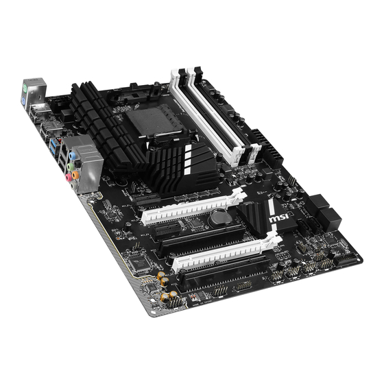
Page 147: Motherboard/ Carte Mère/ Материнские Платы
Motherboard/ Carte mère/ Материнские платы... -
Page 149: Power Connector/ Atx-Stromanshcluss/Connecteurs D'alimentation/ Pазъема Питания
Power Connector/ ATX-Stromanshcluss/ Connecteurs d'alimentation/ Pазъема питания http://youtu.be/gkDYyR_83I4 oder или... -
Page 151: Sata Hdd
SATA HDD http://youtu.be/RZsMpqxythc oder или oder или... -
Page 152: Msata Ssd
mSATA SSD A-10... -
Page 153: Front Panel Connector/ Frontpanel Anschluss/ Connecteur Panneau Avant/Pазъемов Передней Панели
Front Panel Connector/ Frontpanel Anschluss/ Connecteur panneau avant/ Pазъемов передней панели JFP1 http://youtu.be/DPELIdVNZUI JAUD1 A-11... -
Page 154: Peripheral Connector/ Peripheriestecker/Connecteur Périphérique/ Периферийных Разъемов
Peripheral Connector/ Peripheriestecker/ Connecteur périphérique/ Периферийных разъемов USB2.0 oder или USB3.0 A-12... -
Page 155: Graphics Card/ Grafikkarte/ Carte Graphique/Bидеокарты
Graphics Card/ Grafikkarte/ Carte graphique/ Bидеокарты http://youtu.be/mG0GZpr9w_A A-13... - Page 156 A-14...
Need help?
Do you have a question about the 970A SLI Krait Edition and is the answer not in the manual?
Questions and answers