Table of Contents
Advertisement
Quick Links
Advertisement
Table of Contents

Related Manuals for PCB Piezotronics 2305-01A


Summary of Contents for PCB Piezotronics 2305-01A
- Page 1 Model 2305-01A Reaction Torque Sensor Installation and Operating Manual For assistance with the operation of this product,contact: PCB Load & Torque, Inc. Toll-free: 866-684-7107 24-hour SensorLine™: 716-684-0001 Fax: 248-888-8266 E-mail: LTInfo@pcbloadtorque.com Web: www.pcbLoadTorque.com...
- Page 2 Assistance is needed to safely operate equipment PCB Piezotronics is an ISO-9001 certified company whose Damage is visible or suspected calibration services are accredited by A2LA to ISO/IEC Equipment fails or malfunctions 17025, with full traceability to SI through N.I.S.T.
- Page 3 CAUTION Refers to hazards that could damage the instrument. NOTE Indicates tips, recommendations and important information. The notes simplify processes and contain additional information on particular operating steps. The following symbols may be found on the equipment described in this manual: This symbol on the unit indicates that high voltage may be present.
- Page 4 PCB工业监视和测量设备 - 中国RoHS2公布表 PCB Industrial Monitoring and Measuring Equipment - China RoHS 2 Disclosure Table 有害物质 镉 汞 铅 (Pb) 六价铬 (Cr(VI)) 多溴联苯 (PBB) 多溴二苯醚 (PBDE) 部件名称 (Hg) (Cd) 住房 PCB板 电气连接器 压电晶体 环氧 铁氟龙 电子 厚膜基板 电线 电缆 塑料 焊接...
- Page 5 Component Name Hazardous Substances Lead (Pb) Mercury (Hg) Cadmium (Cd) Chromium VI Polybrominated Polybrominated Compounds Biphenyls (PBB) Diphenyl Ethers (Cr(VI)) (PBDE) Housing PCB Board Electrical Connectors Piezoelectric Crystals Epoxy Teflon Electronics Thick Film Substrate Wires Cables Plastic Solder Copper Alloy/Brass This table is prepared in accordance with the provisions of SJ/T 11364.
-
Page 6: Table Of Contents
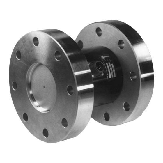
REACTION TORQUE SENSOR OPERATION MANUAL TABLE OF CONTENTS Section Page 1.0 Introduction 2.0 Safety Information 3.0 Mechanical Installation 4.0 Electrical Installation 5.0 Polarity 6.0 Shunt Calibration 7.0 Operation 8.0 Troubleshooting 9.0 Maintenance LIST OF ILLUSTRATIONS Figure Page 1. Flange Mount Reaction Torque Sensor 2. -
Page 7: Introduction
REACTION TORQUE SENSOR OPERATION MANUAL 1.0 INTRODUCTION Gage Committee as revised in May 1960. wiring code is as follows: Reaction torque sensors manufactured by the Force- Torque Division of PCB are strain gage based measuring instruments suitable for a wide range of torque measurement applications. -
Page 8: Safety Information
REACTION TORQUE SENSOR OPERATION MANUAL thrust and bending moment that may be applied without electrical or mechanical damage to the torque sensor. Do not exceed moment (W x S) or shear (W) whichever attained first. Measurement inaccuracy and structure damage may result. Install the sensor in a manner that minimizes these loads. -
Page 9: Electrical Installation
REACTION TORQUE SENSOR OPERATION MANUAL 4.0 ELECTRICAL INSTALLATION As the host structure (diaphragm, bending beam, shear beam, column, etc.) is loaded or stressed, the For proper electrical connections, refer to the Wheatstone Bridge becomes unbalanced, resulting installation drawing for the torque sensor, and the in an output signal that is proportional to the applied wiring drawing for the signal conditioner used. -
Page 10: Operation
REACTION TORQUE SENSOR OPERATION MANUAL 6. Record the value of the signal conditioner’s used. This value, and the particular resistor, are output signal and/or numeric display. This now matched to the transducer and form a basis value is the shunt calibration value, or of the transferable shunt calibration. -
Page 11: Troubleshooting
REACTION TORQUE SENSOR OPERATION MANUAL 8.0 TROUBLESHOOTING Measurement sensors are designed and built to withstand these non-measured forces and bending No output moments (extraneous loads), the errors due to them No power are present. PCB engineers can design the set-up to Loose or dirty connections eliminate or minimize these extraneous loads. - Page 12 REACTION TORQUE SENSOR OPERATION MANUAL Caution should be observed to insure that liquids are not permitted to migrate into devices that are not hermetically sealed. Such devices should only be wiped with a damp cloth and never submerged or have liquids poured on them.
- Page 13 Flange (M24 Bolts) Torsional Stiffness 75,800 klbf-in/radian 8564 kN-m/radian PCB Load & Torque Sensing Element Strain Gage Strain Gage A Division of PCB Piezotronics Housing Material(Sensor) Plated Steel Plated Steel 24350 Indoplex Circle Electrical Connector PT02E-10-6P PT02E-10-6P Farmington Hills, MI 48335 All specifications are at room temperature unless otherwise specified.
- Page 14 PCB Load & Torque Inc. claims proprietary rights in REVISIONS the information disclosed hereon. Neither it nor any reproduction thereof will be disclosed to others without DESCRIPTION the written consent of PCB Load and Torque Inc. UPDATED DIM'S, REMOVED PIN OUT VIEW - 02.23.18, PTE 47634 PUSH/TURN RECEPTACLE (BENDIX PT02E-10-6P OR EQUIV.)
Need help?
Do you have a question about the 2305-01A and is the answer not in the manual?
Questions and answers