
Subscribe to Our Youtube Channel
Related Manuals for RGC HS1000

Summary of Contents for RGC HS1000
- Page 1 HS1000 HYDRAULIC SWING HOIST INSTRUCTIONS REIMANN & GEORGER CORPORATION HOISTING PRODUCTS BUFFALO, NY P/N 6102020 7/12/11...
- Page 2 PRE-HOISTING CHECKLIST This checklist must be checked prior to each use of the hoist. This checklist must be used in conjunction with the maintenance and inspection procedures outlined in this manual. The hoist and related equipment must be thoroughly inspected prior to each use by a trained person. A trained person is one who has read and thoroughly understands this instruction manual and related equipment manuals and, through training and experience, has shown knowledge regarding the safe operational procedures.
- Page 3 PRE-HOISTING CHECKLIST (continued) Insure pin and hairpin between Cylinder Rod and collared Boom plate are connected and in good condition. Insure the two pins and hairpins between the Winch and Counterweight Leg are connected and in good condition. Insure upper and lower sections of Counterweight Leg are bolted together using grade 5 bolts and nuts with shake washers.
-
Page 4: Table Of Contents
SAFETY ............................1 Introduction ..........................1 Safety Definitions ......................... 1 HydraPak And Hoist Safety Labels ....................1 HS1000 Hoist Safety Rules ......................1 SPECIFICATIONS ........................3 Technical Data ..........................3 Nameplate And Serial Number Tag ....................3 INSTALLATION AND SETUP ....................5 Prior To Setup .......................... - Page 5 3-10 Ballast Block Assembly ........................ 13 3-11 Ballast Block Filling ........................13 3-12 Mounting Hand Winch on HS1000 ....................14 HydraPak Controls ........................18 Typical HydraPak/Hoist Positioning ..................... 19 “Hoist” Signal ..........................20 “Lower” Signal ..........................21 “Stop” Signal ..........................21 “Emergency Stop”...
-
Page 6: Safety
1 SAFETY 1.1 INTRODUCTION Your Reimann & Georger Corporation HS1000 Hydraulic Swing Hoist has been engineered to provide lifting performance, long term economics and safety advantages that no other type can match. However, even a well-designed and well-built hoist can malfunction or become hazardous in the hands of an inexperienced and/or untrained user. - Page 7 12. Hoisting area is to be kept clear of unauthorized personnel at all times. Place barricades or secure the area in such a manner that if there were an equipment failure, no personnel would be injured. 13. Keep out from under a raised load. 14.
-
Page 8: Specifications
The hoist label should appear as the sample nameplate shown in Figure 2-1. Record the model and serial numbers, and capacity rating for future reference. HOIST CAP. lbs. MODEL SERIAL NO. Figure 2-1. Typical Hoist Product Nameplate MODEL HS1000 SERIAL NUMBER CAPACITY RATING 1000 LBS. -
Page 10: Installation And Setup
3 INSTALLATION AND SETUP 3.1 PRIOR TO SETUP 1. If the unit is new from the factory, cut the banding and separate the parts. Remove shipping protection on Boom pins and Front Leg sockets. WARNING: ENSURE ALL STRUCTURAL MEMBERS OF THE HOIST ARE FREE OF DEFECTS AND DAMAGE THAT MAY AFFECT THE INTEGRITY OF THE UNIT. -
Page 11: Counterweight Leg Pre-Assembly
Figure 3-1. Front Leg Figure 3-2. Stabilizer 3.3 COUNTERWEIGHT LEG PRE-ASSEMBLY 1. Align the upper and lower sections of the Counterweight Leg as shown in Figure 3-4. 2. Fasten upper and lower counterweight sections together with 1/2” x 1-1/4” Grade 5 bolts and nuts with shake washers as shown in Figure 3-4. -
Page 12: Frame Assembly
WARNING: ENSURE ALL BOLTS BETWEEN UPPER AND LOWER SECTIONS OF COUNTERWEIGHT LEG ARE TIGHT (60-75 FT-LBS.) AND IN GOOD CONDITION. 3.4 FRAME ASSEMBLY 1. Throughout the following procedure, refer to Figure 3-5. Begin by having one person stand the Front Leg vertically. Steady the Front Leg and ensure it is vertically plumb. - Page 13 WARNING: ENSURE PINS AND HAIRPINS AT POINTS “C”, “D”, “E” AND “F” ARE PROPERLY CONNECTED AND IN GOOD CONDITION. ENSURE LOCKSCREWS AT POINTS “B” AND “G” ARE TIGHTENED. CAUTION: DO NOT MOUNT THE HYDRAULIC CYLINDER UNTIL AFTER THE HYDRAPAK IS RAISED TO THE ROOF.
-
Page 14: Mounting The Cylinder
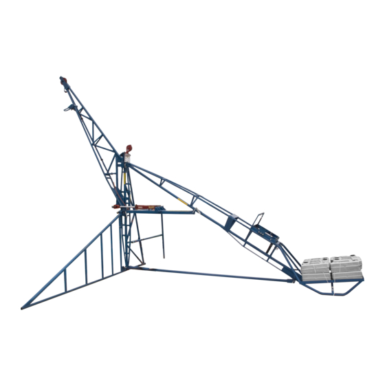
Figure 3-5. Completed Frame Assembly 3.5 MOUNTING THE CYLINDER 1. The cylinder assembly, or cylinder carton, is labeled #0700069 and contains the following parts: Part Number Quantity Description 5000057 Cable Weight 5000214 Screw Lock 0700276 HS1000P Socket 5100718 Bearing SBPSD205-16 S 0704926 Cylinder Assy Hydr HS 2. -
Page 15: Mounting The Winch
3.6 MOUNTING THE WINCH 1. Remove hydraulic connections from Winch before mounting. 2. Place the Winch in position on the Counterweight Leg as shown in Figure 3-7. 3. Secure Winch to Counterweight Leg using the two pins and hairpins. WARNING: ENSURE THE TWO PINS AND HAIRPINS BETWEEN THE WINCH AND COUNTERWEIGHT LEG ARE PROPERLY CONNECTED AND IN GOOD CONDITION. - Page 16 Figure 3-7. Winch Mounting Position 5. Before applying any load, inspect the wire rope for wear as detailed in Chapter 6. WARNING: DISCARD DEFECTIVE WIRE ROPE IMMEDIATELY. 6. Attach shackle and safety hook as shown in Figure 3-9. WARNING: ENSURE SHACKLE AND HOOK HAVE A RATED CAPACITY OF AT LEAST 1000 LBS. AND ARE IN GOOD CONDITION.
-
Page 17: Ballast Block Assembly
Figure 3-8. Cable Keeper Operation Figure 3-9. Single Line Operation Up to 1000 Pounds 3.8 BALLAST BLOCK ASSEMBLY Before using the Ballast Blocks, they must be filled with the proper amount of concrete. Prepare the Ballast Blocks as follows: 1. Place the Ballast Block handle in the base section of the ballast weight. (This is the section without the filling hole.) This handle can stand upright by itself. -
Page 18: Raising The Hydrapak To The Roof Using The Optional Hand Winch
2. Place a funnel into the opening and pour a loosely mixed, flowing concrete into the box. Funnel may require slitting to fit opening of Ballast Block. To achieve the required Ballast Block weight of 50 pounds, fill it completely by positioning it on an angle. - Page 19 See Figure 3-12. Figure 3-12. Mounting Hand Winch on HS1000 3. Before reeving the wire rope, rotate the boom in over the deck and tie securely to the counterweight leg. Using a step ladder with OSHA compliant fall protection, reeve the wire rope through the pivot sheave and then between the cable keeper and the boom sheave.
-
Page 20: Operation
4 OPERATION 4.1 BEFORE OPERATING THE HOIST WARNING: ONLY TRAINED PERSONNEL SHALL OPERATE THIS EQUIPMENT. A TRAINED PERSON IS ONE WHO HAS READ AND THOROUGHLY UNDERSTANDS THIS INSTRUCTION MANUAL AND RELATED EQUIPMENT MANUALS AND, THROUGH TRAINING AND EXPERIENCE, HAS SHOWN KNOWLEDGE REGARDING THE SAFE OPERATIONAL PROCEDURES. -
Page 21: Raising And Lowering The Load
4.2 RAISING AND LOWERING THE LOAD WARNING: ENSURE 1000 LBS. (ONTARIO OHSA: 570 KG.) OF REIMANN & GEORGER CORPORATION APPROVED BALLAST BLOCKS ARE SECURED PROPERLY IN THE LOWER COUNTERWEIGHT BASKET WITH ROPE BEFORE OPERATING THE HOIST. WARNING: NEVER EXCEED THE RATED LOAD CAPACITY OF 1000 LBS. WARNING: NEVER USE HUMAN BEINGS AS COUNTERWEIGHT. - Page 22 WARNING: PERSONNEL MUST NEVER SECURE A LIFE LINE TO THE HOIST FRAME STRUCTURE. Figure 4-2. Typical HydraPak/Hoist Positioning 3. Close the choke to start a cold engine. With control levers in neutral, start the HydraPak and allow to warm up. Open choke slowly after engine starts.
-
Page 23: Hand Signals
WARNING: KEEP OUT FROM UNDER A RAISED LOAD. 7. Use the boom control lever shown in Figure 4-1 to swing the boom 135° to load or unload material on the roof deck where you are working. 8. When lowering the load, gradually decelerate it as it nears the ground. CAUTION: THE WINCH DRUM MUST ALWAYS HAVE AT LEAST THREE TURNS OF WIRE ROPE WHEN THE LOAD IS AT THE LOWEST POINT OF TRAVEL. -
Page 24: Preparing Hoist For Shutdown
Arm extended, palm down, Use one hand to give any motion signal and place other hand motionless in move hand rapidly right and left. front of hand giving the motion signal. (Hoist Slowly shown as example.) Figure 4-6. Figure 4-7. “Emergency Stop”... -
Page 25: Disassembly
5 DISASSEMBLY 5.1 PRIOR TO DISASSEMBLY WARNING: ONLY TRAINED PERSONNEL SHALL DISASSEMBLE THE HOIST. A TRAINED PERSON IS ONE WHO HAS READ AND THOROUGHLY UNDERSTANDS THIS INSTRUCTION MANUAL AND RELATED EQUIPMENT MANUALS AND, THROUGH TRAINING AND EXPERIENCE, HAS SHOWN KNOWLEDGE REGARDING THE SAFE OPERATIONAL PROCEDURES. -
Page 26: Removing Parts From Deck
5.5 REMOVING PARTS FROM DECK When removing any parts from the deck, observe the following safety rules: 1. Use a hoist beam, swing beam or freight elevator to lower the disassembled parts of the hoist to the ground. 2. Safely secure the hoist parts on the transporting medium without overloading before lowering to the ground. 3. -
Page 27: Disassembling The Frame
5.7 DISASSEMBLING THE FRAME WARNING: NEVER DISASSEMBLE THE FRAME NEAR A ROOF EDGE. 1. Insure that the hoist is not supporting any load before proceeding. WARNING: NEVER DISASSEMBLE THE HOIST WITH WEIGHT SUSPENDED FROM THE BOOM. 2. Untie the rope securing the ballast blocks in the Lower Counterweight basket. Remove the ballast blocks and place them where they will not impede dismantling procedures. - Page 28 Figure 5-1. Completed Frame Assembly...
-
Page 29: Inspection And Maintenance
6 INSPECTION AND MAINTENANCE 6.1 GENERAL MAINTENANCE RULES Maintenance information for the associated HydraPak and HydraWinch is in the respective specific manuals for these units. 1. Proper maintenance of the hoist and related equipment consists of adhering to all the guidelines given in this chapter and in the Pre-Hoisting Checklist in the front of this manual. -
Page 30: Initial Inspection
6.2 INITIAL INSPECTION Hoist erection and dismantling must be done by trained personnel only as defined in Section 6.1. Each time after setting up the hoist and before placing it in service, all parts of the structure, boom, hoisting machine, and other equipment must be thoroughly inspected by trained personnel as described in the remainder of this chapter. - Page 31 4. Kinking: Severe kinking, crushing, bird caging or other damage causing distortion of the rope structure. Bird caging is a bulging in the wire rope caused by the individual wires becoming untwisted. This untwisting of individual wires is usually caused by impact loading on the wire rope (such as a sudden stop). 5.
-
Page 33: Troubleshooting
7 TROUBLESHOOTING The following chart is intended to assist with troubleshooting the HS1000 swing hoist. While not all inclusive, the chart outlines the most common causes of a problem and the recommended course of action. Troubleshooting guides for the associated HydraPak and HydraWinch are in the instruction manuals specifically for these units. -
Page 34: Parts List
8 PARTS LIST The following parts list applies to the hoist assembly only. The parts lists for the HydraWinch and HydraPak units are in the separate manuals for these items. Each item number on this parts list can be matched with the item number shown on the Figure 8-1 assembly drawing. - Page 35 Figure 8-1. HS1000 Assembly Drawing...
- Page 36 LIMITED PRODUCT WARRANTY Reimann & Georger Corporation Hoisting and Construction Products A. LIMITED WARRANTY Reimann & Georger Corporation (the “Manufacturer”) warrants to the original purchaser (the “Buyer”) that all Reimann & Georger Hoisting and Construction products shall be free of defects in material and workmanship for a period of one (1) year from date of original purchase.
- Page 37 ADDITIONAL EXCLUSIONS FROM THIS LIMITED WARRANTY. THIS LIMITED WARRANTY DOES NOT COVER ANY OF THE FOLLOWING: 1. Equipment which has been abused, damaged, used beyond rated capacity, or repaired by persons other than authorized service personnel. 2. Damage caused by acts of God which include, but are not limited to, hailstorms, windstorms, tornadoes, sandstorms, lightning, floods, and earthquakes.
- Page 38 9912...
Need help?
Do you have a question about the HS1000 and is the answer not in the manual?
Questions and answers