
Summary of Contents for Prosilica GB660
- Page 1 USER MANUAL December 14, 2009 GB660 GB660C GB660-V GB660C-V Prosilica Inc. www.prosilica.com tel: 604.875.8855 fax: 604.875.8856 © 2009 Prosilica Inc. All rights reserved.
-
Page 2: Table Of Contents
GB660 User Manual 70-0045A-A Table of Contents Table of Contents ..........................ii Introduction ..........................1 Precautions ..........................1 Warranty ............................1 Specifications ..........................2 Supported Features ........................3 Mechanical ..........................4 Connections ..........................7 Cleaning the Sensor ........................11 Adjusting the C-mount ......................12 Camera Installation ........................13 System Optimization .........................18 Trouble Shooting ........................20... -
Page 3: Introduction
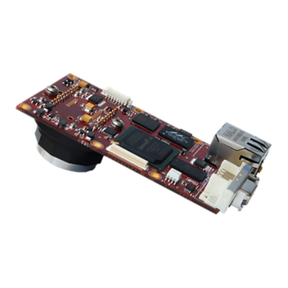
GB660 User Manual 70-0045A-A Introduction The GB660 series of cameras are single board, 120 frames per second, VGA, Gigabit Ethernet cameras based on the Sony ICX618ALA and ICX618AQA, EXview HAD CCD sensors. Precautions READ INSTALLATION GUIDE CAREFULLY. This document contains specific information which is necessary for the correct operation and treatment of this product. -
Page 4: Specifications
GB660 User Manual 70-0045A-A Specifications Sensor Type Sony ICX618ALA CCD (ICX618AQA for color) Sensor Shutter Type Progressive Interline Image Resolution 659 x 494 pixels 5.6μm x 5.6μm Pixel Size Optical Format 1/4 inch Lens Mount C-mount with adjustable back focus (CS-mount available) †... -
Page 5: Supported Features
GB660 User Manual 70-0045A-A Supported Features Imaging Modes free-running, external trigger, fixed rate, software trigger Fixed Rate Control 0.001 fps to maximum frame rate External Trigger Delay 0 to 60 seconds in 1 microsecond increments External Trigger Event rising edge, falling edge, any edge, level high, level low... -
Page 6: Mechanical
GB660 User Manual 70-0045A-A Mechanical 2.00 50.8 0.062 1.6 0.10 2.6 1.80 45.7 0.13 3.2 2 PLCS TYP 6 PLCS TYP 0.21 0.75 19.1 0.17 4.3 0.10 2.5 0.37 9.4 0.62 15.7 M2.5x0.45 MODEL: GB660/GB660C 2 PLCS TYP OPTIONS: LANDSCAPE/RIGHT ANGLE CONNECTORS 0.54 13.6... - Page 7 GB660 User Manual 70-0045A-A 2.00 50.8 0.10 2.6 1.80 45.7 0.062 1.6 0.13 3.2 2 PLCS TYP 6 PLCS TYP 0.21 5.4 0.75 19.1 M2.5x0.45 0.53 13.5 0.63 16 2 PLCS TYP 1.16 29.5 0.93 23.6 0.37 9.4 0.62 15.7...
- Page 8 GB660 User Manual 70-0045A-A 0.84 21.3 0.65 16.5 0.45 11.4 0.29 7.4 ADJUSTABLE C-MOUNT *Nominal value. This dimension will vary INCHES[MILLIMETERS] depending on CCD type. Prosilica Inc.
-
Page 9: Connections
GB660 User Manual 70-0045A-A Connections Figure 1. GB SERIES connection diagram. Prosilica Inc. - Page 10 The General Purpose I/O port uses a 3M 10214-55G3PC (or 3M 10214-6212PC) connector on the camera side. The mating cable connector is 3M 10114-3000PE with shielded housing 3M 10314-3210-00X (X indicates color preference). This connector can be purchased from Prosilica or from http://www.digikey.com.
- Page 11 To operate the camera 12V Power with suitable current capacity (see specifications) must be provided on Pin 1 and the Power Ground on Pin 2. A cable assembly providing this power can be ordered from Prosilica (Prosilica P/N 02-8007A for North America or Prosilica P/N 02-8008A for a Universal supply).
- Page 12 GB660 User Manual 70-0045A-A not isolated and therefore careful attention should be used when designing cabling in noisy environments. Isolated Ground Isolated Ground must be connected to the user’s external circuit ground if Sync Input 1 or Sync Output 1 is to be used.
-
Page 13: Cleaning The Sensor
Repeat this process until the debris is gone. If this process fails to remove the debris, then contact Prosilica. Prosilica Inc. -
Page 14: Adjusting The C-Mount
Use an adjustable wrench to loosen locking ring. Be careful not to scratch the camera. When the locking ring is loose, unthread the ring a few turns from the camera face. A wrench suitable for this procedure can be provided by Prosilica (P/N 11-0048A). Image to Infinity Use a c-mount compatible lens that allows an infinity focus. -
Page 15: Camera Installation
Camera Installation Computer Interface The Prosilica GB Series cameras will work with any Ethernet network card; however Prosilica strongly recommends using Gigabit Ethernet components that support Jumbo Frames. A Jumbo Frame is loosely defined as a frame size greater than 1500 bytes however typical Jumbo Frames are around 9000 bytes. - Page 16 GB660 User Manual 70-0045A-A Gigabit Ethernet Setup for Windows o Install network card in computer. o Boot the PC and cancel the “Found new Hardware Wizard” window that may appear when Windows detects the new card. o Install the driver that came with the network card.
- Page 17 GB660 User Manual 70-0045A-A o Select the Internet Protocol (TCP/IP) check box and then select Properties. See Figure 5. Network card TCP/IP address.. Select the Use the following IP address and enter an IP address of 169. 254. x. y, where x and y can be any number. Press the TAB key after entering the IP address and the subnet mask will automatically be entered.
- Page 18 GB660 User Manual 70-0045A-A Figure 6. Turn off Firewall. o Return to the Gige Local Properties window as in Figure 4. Select the Advanced tab as in Figure 6 and disable the Firewall for this device. Click OK to save changes.
- Page 19 Plug in the Prosilica camera via the Gigabit Ethernet port. Plug in the power connection. Verify that the Status LED 2 is a solid green. Run the Prosilica GigE Viewer Application. It will take a few seconds for the camera to be recognized. If the camera does not appear in the Viewer list after approximately 10 seconds then try disconnecting and reconnecting the power.
-
Page 20: System Optimization
GB660 User Manual 70-0045A-A System Optimization o Open the Network Connections Dialog as follows: From the Windows desktop select start, then select Control Panel, then double click on the Network Connections icon. Double click the relevant network card listed or right-click the relevant network card and select Properties. - Page 21 GB660 User Manual 70-0045A-A Figure 9. Network card advanced settings. o Set Maximum Frame Size or Jumbo Frames to the maximum possible value. A typical value is 9000. If the list contains a property called Receive Descriptors, then change this value to its maximum value.
-
Page 22: Trouble Shooting
Driver Issues TBD. Camera will not trigger Check cabling and connections. Verify that external trigger circuit is providing a compatible trigger signal. Use the Prosilica Viewer program in trigger mode to eliminate possible software issues. Prosilica Inc. -
Page 23: Addendum
GB660 User Manual 70-0045A-A Addendum Prosilica Inc. -
Page 24: Gb Io Schematic
GB660 User Manual 70-0045A-A GB IO Schematic CAMERA INTERNAL CIRCUIT SY NC OUTPUT 1 VDD-3.3 390R FAIRCHILD 1/8W MOCD207M SY NC INPUT 1 LOGIC SY NC INPUT 1 VDD-3.3 200R SY NC OUTPUT 1 ISOLATED GROUND LOGIC SY NC OUTPUT 1... -
Page 25: Isolated Trigger Schematic
GB660 User Manual 70-0045A-A Isolated Trigger Schematic CABLE SIDE USERS TRIGGER CIRCUIT SY NC OUTPUT 1 ISOLATED GROUND SY NC INPUT 1 POWER GROUND POWER GROUND 12V POWER 12V_POWER 3M 10114-3000PE SY NC INPUT 1 (DRIVER) USER POWER RECOMMENDED VALUES... -
Page 26: Non-Isolated Trigger Schematic
GB660 User Manual 70-0045A-A Non-isolated Trigger Schematic USERS TRIGGER CIRCUIT CABLE SIDE POWER GROUND POWER GROUND 12V POWER 12V_POWER 3M 10114-3000PE SY NC INPUT 2 SY NC INPUT 2 (3.3V DRIVER) SY NC OUTPUT 2 SY NC OUTPUT 2 (3.3V RECEIVER) The non-isolated trigger circuit is connected to a Texas Instruments SN74LVC2G241 buffer/driver inside the camera. -
Page 27: Video Iris Schematic
GB660 User Manual 70-0045A-A Video Iris Schematic POWER GROUND POWER GROUND 12V POWER 12V_POWER 3M 10114-3000PE CABLE SIDE LENS POWER VIDEO SIGNAL LENS GROUND JEITA CONNECTOR Prosilica Inc. -
Page 28: Trigger Timing Diagram
GB660 User Manual 70-0045A-A Trigger Timing Diagram Readout Time Trigger Latency Expose Start Registered Delay Exposure Time User Trigger Logic Trigger Exposure Trigger Jitter Readout Interline Time Trigger Ready Imaging Idle Prosilica Inc. -
Page 29: Notes On Triggering
GB660 User Manual 70-0045A-A Notes on Triggering Definitions o User Trigger is the trigger signal applied by the user. o Logic Trigger is the trigger signal seen by the camera internal logic. o Tpd is the propagation delay between the User Trigger and the Logic Trigger. - Page 30 GB660 User Manual 70-0045A-A Triggering during the Readout State o For applications requiring the fastest triggering cycle time whereby the camera image sensor is exposing and reading out simultaneously, then the User Trigger signal should be applied as soon as a valid Trigger Ready is detected.
Need help?
Do you have a question about the GB660 and is the answer not in the manual?
Questions and answers