Table of Contents
Advertisement
Quick Links
Advertisement
Table of Contents

Summary of Contents for Wattsense HUB
- Page 1 Installation Guide Intuitive IoT gateway Made in France 2021-08-V1.3...
-
Page 2: Table Of Contents
In case of LON IP-852 network In case of LON FT10 network To connect the Hub directly to the technical equipment in the absence of a BMS The equipment communicates in Modbus IP The equipment communicates in Modbus RTU (RS485) -
Page 3: What Do You Need Before Starting
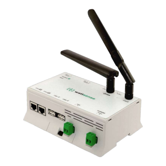
What do you need before starting? Provided material ● Hub ○ Dimensions: 160 x 110 x 55 mm ○ Weight: 340 g ● GSM standard antenna ● LoRa standard antenna ● USb to USB micro cable 2021-08-V1.3... -
Page 4: Required Material
Required material ● Powerline voltage (100 to 250VAC) to 12-24V DC +/-10%, 2A Max. Power supply ● Cable between the power supply and the Hub: 2 wires (red, black), 22 AWG, minimum section: 0.35 mm² ● Flat screwdriver ● Cutting pliers ●... -
Page 5: The Power Supply Of The Hub
○ Mount the Hub on a DIN rail. ○ Or attach 2 screws to a wall and hook the Hub using the notches on the back of the case: Screws of maximum 4 mm in diameter, with a head of maximum... - Page 6 7.5 mm diameter, a spacing of 89.4 mm. ● To avoid any risk of injury caused by the Hub falling, the Hub must not be installed more than 2 meters from the ground. ● Use a DC power supply of 12-24V DC +/-10%, 2A Max.
- Page 7 ● Install the original antenna delivered with the Hub. ● Screw the cable into the power connector of the Hub. 2021-08-V1.3...
- Page 8 ● Connect the cable to the power supply. ● Check that the "Power" LED is lit (steady green light). 2021-08-V1.3...
- Page 9 ● Check that the Hub appears on the console: the presence indicator of the Hub changes from red to green. ● If the Hub appears on the console, it is functional; you can go to the connection step of the Hub to the equipment and/or the network of the building.
-
Page 10: To Connect The Hub To The Bms
To connect the Hub to the BMS ● Determine the type(s) of network(s) associated with the BMS (communication protocols between the BMS server and the technical equipment). ● Obtain, if possible, the schematic of the communication network(s) of the BMS. -
Page 11: In Case Of Ip Network (Except Lon)
Connection: ● Make sure to have an Ethernet cable ● Connect the cable to the Ethernet port of the Hub ETH1 or ETH2. ● Connect the Hub to the switch (IP network) on which the supervision PC/BMS server is connected. - Page 12 ● If there is no DHCP server on the network, attribute a static IP address, its mask and the gateway if necessary to the Hub (Discuss with the building’s IT manager). ● If there is a DHCP server on the network, the address is automatically assigned.
-
Page 13: In Case Of Lon Ip-852 Network
Connection: ● Make sure to have an Ethernet cable. ● Connect the cable to the Ethernet ports of the Hub ETH1 or ETH2. ● Connect the other end of the cable to the IP-852 server on the LON network. 2021-08-V1.3... - Page 14 ● Verify that the ETH1 or ETH2 LED lights up ● Register the IP address of the Hub on the IP-852 server of the LON network; the IP-852 server’s password is probably required. Information to retrieve in preparation for the configuration: ●...
-
Page 15: In Case Of Lon Ft10 Network
In case of LON FT10 network Connection: ● Make sure to have a USB Echelon U60 FT DIN gateway. ● Connect this gateway to the USB port 1 or 2 of the Hub. 2021-08-V1.3... -
Page 16: To Connect The Hub Directly To The Technical Equipment In The Absence Of A Bms
● If you have the NL220 software, export the LON database as an archive file or as an NLC file. To connect the Hub directly to the technical equipment in the absence of a ● Prepare the list of equipment to be connected and their respective communication protocols. -
Page 17: The Equipment Communicates In Modbus Ip
To connect only one equipment ● Make sure to have an Ethernet cable. ● Connect the cable to the Ethernet port of the Hub ETH1 or ETH2. ● Connect the other end of the cable to the equipment. ● Verify that the ETH1 or ETH2 LED lights up. - Page 18 To connect two devices ● Make sure to have two Ethernet cables. ● Connect the cables to the Ethernet ports of the Hub ETH1 and ETH2. ● Connect the cables to the two devices. 2021-08-V1.3...
- Page 19 ● Check that the ETH1 and ETH2 LEDs light up. To connect 3 equipment or more make sure to: ● Have an Ethernet cable for the Hub. ● Have as many Ethernet cables as equipment to connect. ● Have an Ethernet switch.
- Page 20 ● Connect an Ethernet cable to the Ethernet port of the Hub ETH1 or ETH2. ● Connect the other end of this cable to the Ethernet switch. 2021-08-V1.3...
-
Page 21: The Equipment Communicates In Modbus Rtu (Rs485)
● The goal is to create a maximum of 2 networks, each grouping equipment with the same communication configuration and assign them to the 2 RS485 ports of the Hub. ● If the characteristics of the equipment require to set more than 2 homogeneous networks, it is necessary to order another Hub. 2021-08-V1.3... - Page 22 2021-08-V1.3...
- Page 23 To connect the equipment: ● Caution: Do not group together devices with different communication parameters on the same Bus. ● Serial wire the network or each of the 2 networks. 2021-08-V1.3...
- Page 24 ● Connect the network to one of the two RS485 ports of the Hub To configure each one of the equipment: ● Configure the address of the 1st Modbus slave to 1, the 2nd to 2, the 3rd to 3 and so on.
-
Page 25: The Equipment Communicates In Bacnet Ip
To connect one equipment ● Make sure to have an Ethernet cable. ● Connect the cable to the Ethernet port of the Hub ETH1 or ETH2. ● Connect the other end of the cable to the equipment. ● Verify that the LED ETH1 or ETH2 lights up. - Page 26 ● Make sure to have an Ethernet switch. ● Connect the power supply to the switch. ● Connect an Ethernet cable to the Ethernet port ETH1 or ETH2 of the Hub. ● Connect the other end of this cable to the Ethernet switch.
- Page 27 ● Connect all equipment to the switch via the Ethernet cables. To configure each one of the equipment: ● From the technical documentation of the equipment, retrieve its IP address and the BACnet port. ● If the equipment does not have an IP address, assign one to it, 192.168.1.1 for the first device, then 192.168.1.2 for the second device, 192.168.1.3 for the third device, and so on.
-
Page 28: The Equipment Communicates In Lon Ft10
The equipment communicates in LON FT10 To connect the equipment ● Make sure to have an Echelon U60 FT DIN USB Gateway. ● Connect it to the USB port 1 or 2 in the Hub. 2021-08-V1.3... - Page 29 ● Wire the gateway to different devices as you wish, in serial, star, etc. To configure each of the equipment ● Retrieve the Neuron-ID that appears on the equipment. ● Write down the Neuron-ID, brand, model of the equipment, and any identifying information.
-
Page 30: The Equipment Communicates In Lon Ip-852
To connect one or several types of equipment. ● Make sure to have an Ethernet cable. ● Connect the cable to the Ethernet port of the Hub ETH1 or ETH2. ● Connect the other end of the cable to the IP-852 server of the LON network. - Page 31 ● Verify that the LED ETH1 or ETH2 lights up. ● Register the IP address of the Hub on the IP-852 server of the LON network. To configure each one of the different equipment: ● Write down the Neuron-ID, brand, model of the equipment, and any identifying information.
-
Page 32: The Equipment Communicates In Lpb
The equipment communicates in LPB To connect one or several equipement: ● Connect the LPB Bus to the X-Bus port of the Hub. ● For each device, connect its MB cable to the X-Bus(-) port and its DB cable to the (+) port of the Hub. -
Page 33: The Equipment Communicates In Knx
The equipment communicates in KNX To connect one or several equipement: ● Connect the KNX Bus to the KNX Bus port of the Hub. ● For each device, connect its (-) wire to the KNX Bus (-) port and its (+) wire to the KNX Bus (+) port in the Hub. -
Page 34: The Equipment Communicates In M-Bus
The equipment communicates in M-BUS To connect one or several equipement: The maximum unit load that the Hub can handle is three devices (3,6mA). If you want to connect more than three M-bus devices you'll have to use an M-bus signal repeater. -
Page 35: To Connect The Hub To Lorawan Sensors
To connect the Hub to LoRaWAN sensors Install the Hub: ● Install the Hub in a central location to ensure the reception of all sensors. ● If the quality of the LoRa signal is good: keep the original antenna installed on the Hub. -
Page 36: Gsm Antenna
GSM Antenna We recommend connecting the GSM antenna to allow remote support to the Hub when needed. that case: ● Connect the standard GSM antenna supplied with the Hub. ● Wait for the GSM LED to flash. ● If the quality of the GSM signal is good: keep the original antenna installed on the Hub. - Page 37 ● If the signal quality is still insufficient: use a high-gain antenna with a maximum of 10 meters of cable; this antenna can, for example, be moved to the outside or to the other floors to obtain a better signal quality. ●...
Need help?
Do you have a question about the HUB and is the answer not in the manual?
Questions and answers