Table of Contents
Advertisement
Quick Links
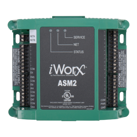
Self-Contained Interoperable Controller Model UCP-1
SUPERSEDES: September 23, 2010
ASM2 . . . . . . . . . . . . . . . . . . . . . . . . . . . . . . . . . . . . . . 3
Overview . . . . . . . . . . . . . . . . . . . . . . . . . . . . . . . . . 3
Features . . . . . . . . . . . . . . . . . . . . . . . . . . . . . . . . . . 3
Purpose of This Guide . . . . . . . . . . . . . . . . . . . . . . . . . 3
Representations and Warranties . . . . . . . . . . . . . . . . . 3
Applicable Documentation . . . . . . . . . . . . . . . . . . . . . . 4
Typical Use . . . . . . . . . . . . . . . . . . . . . . . . . . . . . . . 4
Installation Guide . . . . . . . . . . . . . . . . . . . . . . . . . . . . . 5
Precautions . . . . . . . . . . . . . . . . . . . . . . . . . . . . . . . 5
General . . . . . . . . . . . . . . . . . . . . . . . . . . . . . . . . . . 5
Static Electricity . . . . . . . . . . . . . . . . . . . . . . . . . . . . 5
Location . . . . . . . . . . . . . . . . . . . . . . . . . . . . . . . . . . 5
FCC Compliance . . . . . . . . . . . . . . . . . . . . . . . . . . . 5
Before Installing . . . . . . . . . . . . . . . . . . . . . . . . . . . . . . 5
About this Document . . . . . . . . . . . . . . . . . . . . . . . . 5
Inspecting the Equipment . . . . . . . . . . . . . . . . . . . . 6
What is Not Included with this Equipment . . . . . . . . 6
Equipment Location . . . . . . . . . . . . . . . . . . . . . . . . . 6
Selecting a Power Source . . . . . . . . . . . . . . . . . . . . 6
Installation . . . . . . . . . . . . . . . . . . . . . . . . . . . . . . . . . . 6
Mounting the Device . . . . . . . . . . . . . . . . . . . . . . . . 6
Routing Cabling to the Device . . . . . . . . . . . . . . . . . 7
Grounding the Device . . . . . . . . . . . . . . . . . . . . . . . 8
© 2010 Taco Electronic Solutions, Inc.
Application Guide
ASM2 Auxiliary Sensor Module
Table of Contents
Wiring Information . . . . . . . . . . . . . . . . . . . . . . . . . . . . 8
Connecting Input Devices . . . . . . . . . . . . . . . . . . . . 8
Other Connections. . . . . . . . . . . . . . . . . . . . . . . . . . 9
Specifications . . . . . . . . . . . . . . . . . . . . . . . . . . . . . . . . 9
Electrical . . . . . . . . . . . . . . . . . . . . . . . . . . . . . . . . . 9
Mechanical. . . . . . . . . . . . . . . . . . . . . . . . . . . . . . . 10
Application Overview . . . . . . . . . . . . . . . . . . . . . . . . . 11
Sequence of Operation . . . . . . . . . . . . . . . . . . . . . . . 12
Outdoor Air Temperature. . . . . . . . . . . . . . . . . . . . 12
Outdoor Air Humidity . . . . . . . . . . . . . . . . . . . . . . . 12
Supply Water Temperature . . . . . . . . . . . . . . . . . . 12
Indoor Humidity . . . . . . . . . . . . . . . . . . . . . . . . . . . 12
Energy Consumption Monitoring . . . . . . . . . . . . . . 12
Unit Enable . . . . . . . . . . . . . . . . . . . . . . . . . . . . . . 12
Automatic Configuration . . . . . . . . . . . . . . . . . . . . 13
Controller Identification . . . . . . . . . . . . . . . . . . . . . . . 14
Inputs . . . . . . . . . . . . . . . . . . . . . . . . . . . . . . . . . . . 14
Configuration . . . . . . . . . . . . . . . . . . . . . . . . . . . . . 14
Troubleshooting . . . . . . . . . . . . . . . . . . . . . . . . . . . . . 14
Diagnostic LEDs . . . . . . . . . . . . . . . . . . . . . . . . . . 14
Troubleshooting Tips . . . . . . . . . . . . . . . . . . . . . . . 15
505-008
EFFECTIVE: November 12, 2010
1
Advertisement
Table of Contents

Summary of Contents for iWorX ASM2
-
Page 1: Table Of Contents
ASM2 ........3... - Page 2 Auxiliary Sensor Module THIS PAGE LEFT BLANK INTENTIONALLY 505-008, Effective: November 12, 2010 © 2010 Taco Electronic Solutions, Inc.
-
Page 3: Asm2
Document is being used. The iWorX® ASM shall only be used for the applications identified in the product specifications and for no other pur- poses. For example, the iWorX® ASM is not intended for use to support fire suppression systems, life support systems, critical care applications, commercial aviation, nuclear facilities or any other applications where product failure could lead to injury to person, loss of life, or catastrophic property damage and should not be used for such purposes. -
Page 4: Applicable Documentation
APPLICABLE DOCUMENTATION See the table below for additional documentation that may be applicable to this controller. Description Audience Purpose iWorX® LCI2 Application Guide, Doc- – Application Engineers Provides instructions for setting up and using ument No. 505-002 – Installers the iWorX® Local Control Interface. -
Page 5: Installation Guide
United States. BEFORE INSTALLING About this Document The instructions in this document are for the ASM2 module, which provides global sensor inputs to other iWorX control- lers. 505-008, Effective: November 12, 2010... -
Page 6: Inspecting The Equipment
ASM Inspecting the Equipment Inspect the shipping carton for damage. If damaged, notify the carrier immediately. Inspect the equipment for damage. Return damaged equipment to the supplier. What is Not Included with this Equipment • A power source for the equipment electronics and peripheral devices. -
Page 7: Routing Cabling To The Device
ASM Figure 1: Mounting Dimensions Routing Cabling to the Device Cabling used to connect the power source and cabling used to connect the FTT-10A network must remain separated within the control enclosure and wiring conduit. 505-008, Effective: November 12, 2010... -
Page 8: Grounding The Device
For best performance, connect the power supply common terminal (T38) to the same external point as the ground terminal (T40). WIRING INFORMATION WARNING: Terminals 4,6,9,12,15,18 and 38 are connected internally on all ASM2 controllers. Disconnect ALL power sources when installing or servicing this equipment to prevent electrical shock or equipment damage. -
Page 9: Other Connections
ASM Outdoor Air (OAT) To connect the Outdoor Air thermistor to the unit, attach one wire from the thermistor to OAT (T17) and the other wire to the adjacent common (T18). The thermistor used must be 10K Precon Type III. -
Page 10: Mechanical
ASM Indoor Humidity • 0-10 Volts DC Energy Monitor, End of Interval • Normally open • Dry contact • 5 Volts DC Max Unit Enable • Normally open (closed when active) • Dry contact • 5 Volts DC Max... -
Page 11: Application Overview
ASM Environmental • Temperature: 32 °F to 140 °F (0 °C to 60 °C) • Humidity: 0 to 90%, non-condensing Agency Listings • UL Listed for US and Canada, Energy Management Equipment PAZX and PAZX7. Agency Compliances • FCC Part 15 Class A... -
Page 12: Sequence Of Operation
ASM SEQUENCE OF OPERATION This section describes the sequence of operation for the controller. Outdoor Air Temperature The outdoor air temperature sensor input is for a thermistor. The controller reads the sensor and converts it to a tem- perature once a second. The converted value is made available as a network variable output. -
Page 13: Automatic Configuration
Once the service pin has been pressed, no further action is required by the user; the controller is fully accessible to the LCI. Users may bind to SNVTs on the ASM2 with LNS or other L ORKS tools if they wish. -
Page 14: Controller Identification
ASM, and the meanings and default values for controller parameters. For more information on using the LCI2, see the LCI2 Application Guide. Inputs The Inputs screen displays the current values of the ASM2’s inputs. These values cannot be changed. Input Range... -
Page 15: Troubleshooting Tips
– Green when there is network activity – Off when there is no network activity Service – Illuminated when the service pin is depressed or when a controller gets configured by the LCI. Figure 4: ASM2 Controller LEDs Status Network Service Troubleshooting Tips This section provides remedies for common problems. - Page 16 Getting Help Components within an iWorX® controller, sensor, or power supply cannot be field repaired. If there is a problem with a unit, follow the steps below before contacting your local TES representative or TES technical service.
- Page 17 Taco Electronic Solutions, Inc. is a subsidiary of Taco, Inc. Visit our web site at: http://www.taco-hvac.com Printed in the USA iWorX® and iView® are registered trademarks of Taco Electronic Solutions, Inc. © 2010 Taco Electronic Solutions, Inc. LON, LONWORKS, & LONMARK are trademarks of Echelon Corporation...
Need help?
Do you have a question about the ASM2 and is the answer not in the manual?
Questions and answers