Advertisement
Quick Links
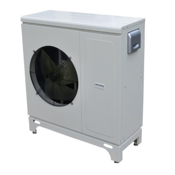
By Heat IQ
INVERTER HP's
PV Integration
compatible
Mitsubishi Compressor inside
Operation, installation & maintenance NZ AU.
IQ AS7V1Ph IQ AS10V /1Ph
IQ AS15V /1Ph
IQ AS20V /3Ph
Installation of this unit must adhere to Local NZ AU
Building Codes and Standards.
Read this manual before installing and or operating the appliance
*
Please pay particular attention to the sections
Leave the manual with the end user/appliance
rd
3
Edition appliances from 1/10/21
0
Advertisement

Summary of Contents for Heat IQ EcoLogic IQ AS7V1Ph
- Page 1 By Heat IQ INVERTER HP’s PV Integration compatible Mitsubishi Compressor inside Operation, installation & maintenance NZ AU. IQ AS7V1Ph IQ AS10V /1Ph IQ AS15V /1Ph IQ AS20V /3Ph Installation of this unit must adhere to Local NZ AU Building Codes and Standards.
- Page 2 Sectional index Pre installation System configurations * Working principal * Plumbing and electrical connections User instruction Engineer and manufacture settings Detailed operation principals Maintenance and alarms Technical information Sensor resistance tables Parts identification Service record Important note for installers Compressor crankcase heater ▪...
- Page 3 Important Safety considerations - Please read before working on this appliance To avoid issues that could damage to the appliance or cause injury this appliance must be installed by a suitably qualified competent contractor. All electrical wiring associated with the appliance must be completed by a licensed electrical contractor in accordance with NZ / AU Standards.
- Page 4 Installation Location ▪ This appliance must be installed outside on a concrete pad foundation not connected to the house foundation. ▪ If operating in temperatures below 0°C for prolonged periods or locations where the snow may fall the base must be raised. we recommend 200 mm above ground to avoid ice build-up on the unit’s chassis. ▪...
-
Page 5: System Configuration
System configuration System Overview 1: Under-floor heating only. Buffer or hydraulic separator as required by the system design ② LPS ET Distribution manifold and pump station as required by the system ③ ① design ④ HEAT PUMP System Overview 2: Heating, Cooling DHW Production and Boiler back up. - Page 6 Description Included ? Description Include Circulation pump Internal Inlet water temperature sensor Internal 3 way Valve External Outlet water temperature sensor Internal External Hot water tank ambient temperature sensor Internal External Soft joint Domestic hot water temperature Internal External sensor sensor Shut-off valve Discharge gas temperature Internal...
-
Page 7: Installation
INSTALLATION Pipe - system connections It is important that you follow the installation information provided here. Pipework and valve train requirements must be in line with the schematics on page 4 or as prescribed in the system design provided by the distributor. 1. -
Page 8: Electrical Connections
Electrical connections All voltage connections must only be carried out by a suitably qualified electrician. Note The Carel HP user interface and RJ10 connection cable are shipped within the HP Cabinet An additional cable can be ordered seperatly from the regional distributor for install at pre wire. ▪... - Page 9 Control connections continued Heating function switching control connections There are two possible methods to turn ON/OFF the Heating function ( settable via SF14) (A/C) If SF14 is set to, “keyboard” (the factory default setting). Then external system controls do not control the unit, the Carel user interface maintains control over the appliance.
- Page 10 DHW Three Way Valve Connection (NO7 NC7) Where DHW is optioned A motorised 3 way valve must be used If the valve used is power open power close then terminals 7-8-9 at the HP are used If the valve is power open –spring return then only terminals 8 and 9 at the HP are used. For hydronic connection of the 3 way valve refer to "system overviews"...
- Page 11 PV Ready Optional Shown above are a Typical DHW cylinder, and the Heat IQ Eco+ combi tank Using the conventional cylinder • The cylinder is piped via a three-way valve from the primary flow and return. these connections for the cylinder coil F/R are made in the line before the hydraulic separator or buffer tank.
- Page 12 1. Add the correct percentage of suitable glycol antifreeze to the water circuit. For example You can purchase Kamco Freezbreaker from Heat IQ (NZ) Freezbreaker at a dose of 12.5 % volume in the system gives protection to - 6 / 25% to -12 / 40% to – 20 ) 2.
- Page 13 User Guide (User Interface - Display & buttons) 13/09/15 15:16 Starting Inlet. 15.6℃ Outlet. 21.4℃ Ambient . 10.9℃ Hot water. 44.9℃ p GD1 user i nter face CAREL Operating buttons Button Name Operation This button will flash to indicate when an alarm occurs. <Alarm>...
- Page 14 Interface Menu Tree Menus Alarm User Unit on/off Parameter Clock input/output history Manu- Service facturer EV01 SF01 ST01 DF02 UI01 CM01 CN01 EV05 SF06 AR01 ST11 EV03 SF05 ST02 DF03 CM02 CN02 EV06 SF07 AR02 ST12 UI02 EV04 SF13 SF14 ST10 EV14 SF09...
- Page 15 Main menu: Press button to enter main menus: Remark: this will not appear if unit on/off for A. Unit on/off A/C(heating) & DHW heating or hot water method is by remote. B. I/O input/output C. Clock D. User E. Service F.
- Page 16 A/C (Heating) and DHW are now successfully switched on. “Starting” displays on the screen, the water pump turns on and the pump symbol displays on the screen. Within some minutes of delay, the fan and compressor will turn on and their respective symbols will also display the on screen.
- Page 17 Changing Set points (user parameters) Display Procedures Press <Prg> to display the main menu, press Down button to User, Press the Main menu Enter button, Press the Down button to the desired parameter. A. Unit On/off B. Input/Output C. Clock D.
- Page 18 Time-zone on/off Timezone on/off TR09:AC timezone Disable TR10:HW timezone Disable The time-zone function activates the pre-set timer programs. A time-zone function is only valid when unit on/off method is “by keyboard”. TR10: HW time-zone is for domestic hot water. When TR10 is enabled, two different time periods are available to set in every day from Sunday to Saturday.
-
Page 19: Weather Compensation
Weather compensation Heating – Weather compensation curve setting Note this function is not appropriate in all applications Users: Seek professional advice before attempting to set weather compensation There are two methods for temperature control: fixed and changeable temperature. Fixed temperature is a fixed value and directly set by the user from the settings area. - Page 20 Changing either ST02 or ST06 will change the heating curve. Increasing ST02 will lift up the curve Control temperature T(heating) ℃ -30℃ Outside temperature (OT) Increasing ST06 will increase the grade of the curve Control temperature T(heating) ℃ -30℃ Outside temperature (OT) The calculated control water temperature will not be allowed over ST14,or under than ST13.
- Page 21 ◆ Setting up the heating compensation curve Heat compensate S T06 0 .6 -5.0 A ct ual s etp: 44.0 Press to change ST06, (OT the actual measured ambient outdoor temp, is displayed). Actual Heating Control temp. RT is also displayed. Press to menu : Heat compensate...
- Page 22 Smart Grid UK-EU - SG READY – (Smart Grid) Some EU countries and other jurisdictions adopt smart meters, providing varying electricity tariff rates. This appliance is approved for use with, and can be applied to these systems. (This option may not currently be applicable for New Zealand, Australia) 1.) Connectors D3-D4 (DI6) is connected to SG1 and D1-D2 (DI7) is connected to SG2 of the electric meter SG signal.
- Page 23 Any changes may cause the unit to fail and will automatically void the appliance warranty. Access to Manufacturer level parameters requires you to seek the passcode from your Regional supplier. Tradepoint Ltd, (heat IQ) for NZ and AU Customers, 0064 6 3447392...
- Page 24 Service engineer level Parameters: Descriptions De- fault Min. Max. Unit Parameter Software version A5202 Information EVO1 Pump by regulation Inlet/outlet water temperature difference EV03 ℃ setting for cooling mode Inlet/outlet water temperature EV04 ℃ difference setting for heating mode SF01 Unit type Only heating or Cooling + Heating SF05...
- Page 25 Manufacturer level parameters Access restricted see note on P23 Para- Descriptions Min. Max. Unit meter fault CM02 Compressor minimum OFF time 1000 Sec. 60 ( AS07V CM11 Rated cooling speed CM13 CM12 70 ( AS10V AS15V AS20V 70 ( AS07V CM12 Max cooling speed 75 (...
- Page 26 Manufacturer parameters continued SF25 PWM pump PID control factor :KP 50.0 SF26 PWM pump PID control factor: TI SF27 PWM pump PID control factor: TD SF28 PWM pump PID control: sampling interval SF29 PWM pump PID: frequency sampling interval ℃ SF30 EVI valve open set temp.
- Page 27 Detailed Principal of Operation Guide for engineers Cooling demand In: RT On: RT>T(cooling)+ST03(T(cooling) is the control water temperature on cooling mode) Off: RT<T(cooling)-1.5℃ and running frequency of the compressor has reduced to Minimum and lasts for 120s. T (cooling) calculation: Default ST01= 13, ST08=0.6 1.) When SF04= No, there is no cooling curve.
- Page 28 Control process Turn process for heating mode 1.) Water pump Starts, - checks water flow. 2.) if water flow meets the requirement and there is heating demand, - fan and compressor start. Turn process for heating mode 1.) Compressor switches off. 2.) After 5 second’s delay, fan motor switches off.
- Page 29 Compressor running control 1.) In cooling mode, when RT≤T (cooling) -0.5℃,compressor runs with minimum frequency. When RT≤T (cooling)-1.5℃,after running for 120 seconds with minimum frequency, compressor is switched off. When ST≤7℃ The compressor runs with minimum frequency. When ST≥8℃. The compressor runs with normal PID control. 2.) In heating mode, when RT≥T(heating) +0.5℃, compressor runs with minimum frequency.
- Page 30 If the compressor running frequency reduces to 40Hz and the compression ratio is no more than 8 for a continual 5 seconds, the compressor runs with 40Hz. if the compression ratio is still more than 8 in a continual 5 seconds, the compressor is switched off and re-switched on again after 3 minutes' delay.
- Page 31 EC fan input control voltage and speed table Series No. Input control Voltage Speed (rpm) 2.8V 2.9V 3.0V 3.1V 3.2V 3.3V 3.4V 3.5V 3.6V 3.7V 3.8V 3.9V 4.0V 4.1V 4.2V 4.3V 4.4V 4.5V 4.6V De-icing heater running control When all of conditions below are met, the de-icing heater is switched on 1.) Compressor is ON;...
- Page 32 Defrosting mode activation conditions (1 (all must be met) a.) The unit running time after previous defrosting must be ≥DF06 b.) Temperature differential OT minus LPS ≥△T and last for DF05 time period . △T=DF04-4*(CM15-CMF)/(CM15-CM16), (CMF is current compressor running frequency) c.) LPS ≤DF02 and lasts for DF11 time.
-
Page 33: Routine Maintenance
Routine maintenance. Unit Refrigerant Checks 1. Check the operation of the high-pressure and low pressure transducers. Replace if there is a fault. 2. Check for fouling of the filter (by checking the temperature difference in the copper piping either side). Replace it if necessary. - Page 34 Alarms. Alarms are divided into two groups : Auto reset alarms, & Manual reset alarms. 1. For auto reset alarms, the user is not required to acknowledge the alarm or reset the appliance. 2. The corresponding device will be automatically be restarted once the alarm status disappears. 3.
- Page 35 Alarms relating to inverter board (auto reset) AL100 IPM overcurrent AL101 Compressor. drive failure AL102 Compressor. overcurrent AL103 Power phase loss AL104 IPM current sampling error AL105 Radiator overheat AL106 Pre-charging failure AL107 DC bus overvoltage AL108 DC bus under voltage AL109 AC input under voltage AL110...
- Page 36 Alarms in detail 1.) Low pressure protection (Code: AL01) After starting the compressor, it checks the low pressure after AR09 delay. If LPS≤AR31 in continual 120 seconds, then compressor is switched off, 5 seconds later, fan motor is switched off, other parts keep their original state. Alarm code AL01 display on the user interface.
-
Page 37: Technical Information
Temperature Sensor faults (B1-B8 fault are auto reset) If temperature sensors B1 to B8 are below -35C or higher than 120C, a sensor fault is triggered. sensor code Unit's actions to deal with the fault ST replaces RT as temperature control reference. control water temperature +5C on heating mode, AL71 (RT) -5C on cooling mode. - Page 38 AS07V AS10V...
- Page 39 AS15V 1060 AS20V...
- Page 40 Removing the Cabinet IQ AS7V & AS10V The panels must be removed as the order: front panel – back panel – right panel-top panel 1. Unscrew the screws on the right front panel (below left) panel can be removed by pushing downward. 2.
- Page 41 Removing the cabinet IQAS15V The panels must be removed in the order: front right panel – right panel - fan panel - top panel 1. Unscrew the screws on the right front panel (below left) and remove by pushing it downward. 2.
- Page 42 Removing the Cabinet IQAS20V Panels must be removed in order: front right panel – right side panel – front grill - top panel – front left panel 1. Unscrew the screws at the bottom (below left) the front right panel can be taken out by pushing downwards. 2.
- Page 43 Water Pressure Plots AS07V AS10V AS15V AS20V Refrigerant specification – Always confirm and default to Data-plate on the appliance Model AS07V AS10V AS15V AS20V The heat pump contains R410A R410A R410A R410A fluorinated greenhouse gases R410A global warming potential 2088 2088 2088 2088...
- Page 44 Internal pump curve for AS07V AS10V Internal pump curve for AS15V Internal pump curve for AS20V...
- Page 45 Temperature and sensor resistance table NTC All sensors are all NTC10K. Except B5 which is a PT sensor - see pages 47 to 49 R25 :10.0 kΩ±1% B25/50:3470K±1% T (℃) Rmin [ KΩ ] Rnom [ KΩ ] Rmax [ KΩ ] 123.5 128.0 132.5...
- Page 46 Temperature and sensor resistance table NTC 13.57 13.75 13.93 13.04 13.20 13.37 12.53 12.68 12.83 12.04 12.18 12.32 11.57 11.70 11.84 11.13 11.25 11.37 10.70 10.81 10.93 10.29 10.40 10.50 9.900 10.00 10.10 9.522 9.621 9.721 9.160 9.259 9.359 8.814 8.931 9.012 8.483...
- Page 47 Temperature and sensor resistance table NTC 2.164 2.218 2.274 2.098 2.152 2.207 2.036 2.088 2.142 1.975 2.027 2.080 1.917 1.976 2.019 1.860 1.910 1.961 1.806 1.855 1.904 1.753 1.801 1.851 1.702 1.749 1.797 1.653 1.699 1.746 1.606 1.651 1.697 1.560 1.604 1.650 1.515...
- Page 48 Temperature and sensor resistance table PT Only for the PT sensor B5 R25=50KΩ±2% B25/50=3950K ±2% T (℃) Rmin [ KΩ ] Rnom [ KΩ ] Rmax [ KΩ ] 441.8 471.5 503.0 417.9 445.5 474.7 395.5 421.1 448.2 374.4 398.2 423.4 354.5 376.7...
- Page 49 Temperature and sensor resistance table PT T (℃) Rmin [ KΩ ] Rnom [ KΩ ] Rmax [ KΩ ] 49.00 50.00 51.00 46.87 47.86 48.86 44.83 45.83 46.83 42.90 43.89 44.89 41.06 42.05 43.04 39.31 40.29 41.27 37.64 38.61 39.59 36.05 37.01...
- Page 50 Temperature and sensor resistance table PT T (℃) Rmin [ KΩ ] Rnom [ KΩ ] Rmax [ KΩ ] 7.119 7.544 7.991 6.877 7.293 7.731 6.645 7.051 7.480 6.421 6.819 7.238 6.207 6.595 7.005 6.000 6.380 6.781 5.801 6.173 6.565 5.610 5.973...
-
Page 51: Component Parts
Component parts IQ AS07V AS10V 1. Finned coil heat exchanger 6 7 8 9 10 2. Grill 3. Panasonic EC Fan motor 4. De-icing heater 5. Fan blade 6. Inverter board 7. EMC filter 8. EC fan motor board 9. Circulation pump flow feedback 10. - Page 52 IQ AS15V 15 14 13 12 1. Finned coil heat exchanger 2. Fan blade 3. Grill 4. De-icing heater 5. Adjustable feet 6. HP transducer 7. Accumulator 8. HP service connection 9. LP transducer 10. LP service connection 11. 4 way valve 12.
- Page 53 IQ AS20V 3Ph 1. Finned coil heat exchanger 6 7 8 9 10 2. Panasonic EC Fan motor 3. Fan blade 4. De-icing heater 5. Harmonic filter 6. Capacitors board 7. Inverter board 8. Panasonic EC fan motor board 9. Circulation pump flow feedback board 10.
- Page 54 Technical Specifications, by model IQ AS07V Model Number (Indent Model) Heating performance Min. Nominal Max. Heat output/Power consumption/COP at A7/W35℃ 1.92/0.43/4.46 6.69/1.47/4.67 8.64/2.02/4.18 Heat output/Power consumption/COP at A2/W35℃ 1.39/0.44/3.13 5.54/1.62/3.42 6.32/1.92/3.30 Heat output/Power consumption/COP at A-7/W35℃ 3.08/1.16/2.65 4.40/1.39/3.09 5.61/1.83/2.98 Heat output/Power consumption/COP at A-10/W35℃ 2.76/1.12/2.46 3.92/1.37/2.86 5.10/1.79/2.85...
- Page 55 IQ AS10V nz Model Number Heating performance Min. Nominal Max. Heat output/Power consumption/COP at A7/W35℃ 2.72/0.61/4.42 9.90/2.17/4.56 12.38/2.94/4.21 Heat output/Power consumption/COP at A2/W35℃ 2.29/0.76/3.01 8.38/2.36/3.54 10.21/3.02/3.38 Heat output/Power consumption/COP at A-7/W35℃ 2.53/1.20/2.25 6.56/2.25/2.92 8.24/2.82/2.96 Heat output/Power consumption/COP at A-10/W35℃ 2.25/1.16/1.94 5.66/2.25/2.51 7.25/2.86/2.53 Heat output/Power consumption/COP at A-15/W35℃...
- Page 56 IQ AS15V nz Model Number Heating performance Min. Nominal Max. Heat output/Power consumption/COP at A7/W35℃ 3.70/ 0.79/4.68 15.90/ 3.90/ 4.08 16.5/ 4.13/ 4.00 Heat output/Power consumption/COP at A2/W35℃ 3.50/ 1.14/ 3.07 12.60/ 3.54/ 3.56 13.10/ 3.88/ 3.38 Heat output/Power consumption/COP at A-7/W35℃ 3.80/ 1.80/ 2.11 9.84/ 3.38/ 2.91 10.34/ 3.63/ 2.85...
- Page 57 IQ AS20V Model Number Indent appliance Heating performance Nominal Heat output/Power consumption/COP at A7/W35℃ 9.03/1.91/4.72 20.03/4.89/4.09 24.72/6.76/3.65 Heat output/Power consumption/COP at A2/W35℃ 7.58/1.96/3.86 17.63/4.91/3.59 21.7/6.57/3.3 Heat output/Power consumption/COP at A-7/W35℃ 5.69/2.2/2.58 13.4/4.72/2.83 16.23/6.25/2.59 Heat output/Power consumption/COP at A-10/W35℃ 4.75/1.5/3.16 12.05/4.61/2.61 15.33/6/2.55 Heat output/Power consumption/COP at A-15/W35℃...
- Page 58 Service record and notes Service date Notes...
- Page 59 PO Box 530 Whanganui sales@heatiq.co.nz Specifications within this manual may be subject to change without notice NZ edition 2021/10 V4 Reproduction of this manual or on line posting is not permitted without the consent of Tradepoint Ltd Heat IQ ©...
Need help?
Do you have a question about the EcoLogic IQ AS7V1Ph and is the answer not in the manual?
Questions and answers