
Related Manuals for NSK Bruel & Kjaer Vibro VCM-3


Summary of Contents for NSK Bruel & Kjaer Vibro VCM-3
- Page 1 Instruction VIBRO Condition Monitoring 3 VCM-3 On-site Commissioning Keep it accessible for future reference UNRESTRICTED DOCUMENT...
- Page 2 Trademarks and Copyrights All trademarks, service marks, and/or registered trademarks used in this document belong to BK Vibro America Inc., except as noted below: Microsoft®, Microsoft® software, Windows®, Windows® operating system are either registered trademarks or trademarks of Microsoft Corporation in the United States and/or other countries. Trademarks used herein are the property of their respective owners.
-
Page 3: Table Of Contents
Brüel & Kjær Vibro │Instruction VCM-3 On-Site Commissioning Table of Contents Table of Contents Introduction ......................4 Scope ..............................4 Firmware version ..........................5 Document Conventions ........................5 On-site Commissioning of VCM-3 ................6 Prerequisites ............................6 Initial Power Up test – Visual check ............... 7 Investigation of deviations in LED colors after initial power up ............ -
Page 4: Introduction
Introduction Scope The purpose of the On-site commissioning procedure is to bring the VCM-3 in an operational state. • To check that the VCM-3 boots up correctly. • To verify that all channels which shall be used for monitoring the machine, are wired correctly and responds correctly to a tap test. -
Page 5: Firmware Version
Brüel & Kjær Vibro │Instruction VCM-3 On-Site Commissioning Introduction Firmware version Different firmware versions behave differently and looks (slightly) different. This version of the document describes the look and feel of firmware version 1.22. Older versions as used in the drawings will in general look the same but can have vital differences in what a LED color means. -
Page 6: On-Site Commissioning Of Vcm-3
On-site Commissioning of VCM-3 Prerequisites To complete the on-site commissioning procedure, the following must be available: A service laptop with: 1. A Microsoft Edge browser or Mozilla Firefox browser. Due to the installed security certificates on the VCM-3 the Google Chrome browser has difficulties in showing the VCM-3 Homepage. When you address the VCM-3 Homepage in either Microsoft Edge or Firefox some security alerts are shown. -
Page 7: Initial Power Up Test - Visual Check
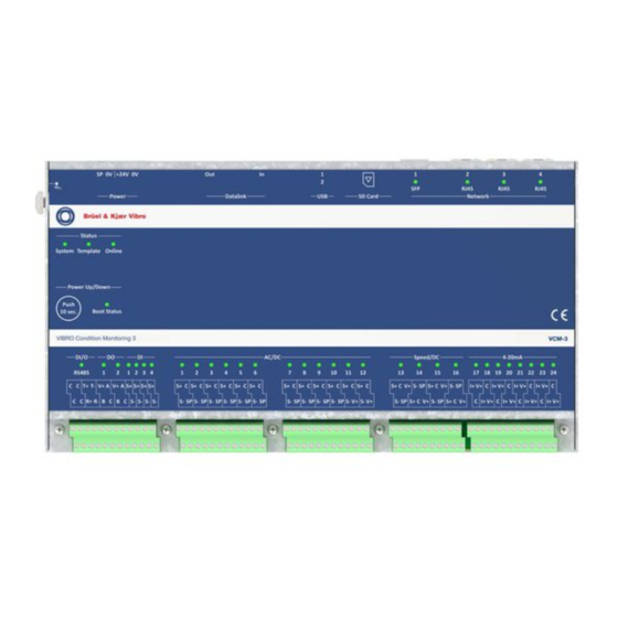
Brüel & Kjær Vibro │Instruction VCM-3 On-Site Commissioning Initial Power Up test – Visual check Initial Power Up test – Visual check Purpose: 1. To check that the VCM-3 can boot up correctly 2. To check that sensors are wired correctly 3. - Page 8 Initial LED status from factory Inputs/Outputs/System and Explanation associated LED color Off – as the VCM-3 is not connected to any network (beside Network RJ-45 connector) On – Blue, indicates that the VCM-3 is not connected to a Status: System ...
-
Page 9: Investigation Of Deviations In Led Colors After Initial Power Up
Brüel & Kjær Vibro │Instruction VCM-3 On-Site Commissioning Initial Power Up test – Visual check Investigation of deviations in LED colors after initial power up It is recommended to remedy any visible problems, if possible, before you proceed with the remaining part of the commissioning procedure. -
Page 10: Non-Ccs Sensors
3.1.3 Non-CCS sensors Color Explanation Blue Sensor is not connected. Sensor is not connected correctly (S+ and S- interchanged). Check the sensor’s calibration. Check the allowed range in the template and the bias level in the tap test. Blue For non-CCS sensors this is indicating a serious problem with the sensor. - Page 11 Brüel & Kjær Vibro │Instruction VCM-3 On-Site Commissioning Initial Power Up test – Visual check Device Status / Explanation LED color On – Red. Watchdog about to reboot the VCM-3 Status: System Action: If watchdog reboot does not help, make a manual reboot. The reboot activates some repair facilities.
-
Page 12: Vcm-3 Homepage Commissioning Procedure
VCM-3 Homepage Commissioning Procedure After the visible inspection check the on-site commissioning procedure shall be continued using the functionality of the VCM-3 Homepage. Via the Homepage the following steps shall be completed: 1. Check the VCM-3 firmware version 2. Check the Operational Status 3. -
Page 13: Check The Vcm-3 Firmware Version And Update Firmware
VCM-3 Homepage Commissioning Brüel & Kjær Vibro │Instruction VCM-3 On-Site Commissioning Procedure Use the following credentials: Username: vcm_service Password: VCM3-Service Check the VCM-3 firmware version and update firmware Check firmware version After the login procedure is completed chack the firmware version number is located in the page header. -
Page 14: Check The Operational Status
Check the Operational Status NOTE! This page is only available on VCM-3 with installed firmware version 1.15 or higher. How to inspect the Operational Status page After login the Operational Status page is shown. This page gives an overview of the present status of the VCM-3. -
Page 15: Check Bias Voltages Of Sensors
VCM-3 Homepage Commissioning Brüel & Kjær Vibro │Instruction VCM-3 On-Site Commissioning Procedure Check bias voltages of sensors Use the Commissioning Report feature to check the bias voltages of the connected sensors. NOTE! The Commissioning Report is only supported with an activated Factory Monitoring Template, which is not to be exchanged with the Standard (Master) Monitoring Template and/or the customized Monitoring Template created with the VCM-3 Editor software. -
Page 16: Make Tap Test Of The Accelerometers
Make tap test of the accelerometers With the tab test can check the signal from each of the connected accelerometers and the speed sensor by using the Oscilloscope function of the VCM-3 Homepage. In addition, it can be checked whether the sensors are connected correctly to the VCM-3 input channels. NOTE! The intended use of the Oscilloscope function is during commissioning to check the input channel signal (raw sensor signal). -
Page 17: Configuration
VCM-3 Homepage Commissioning Brüel & Kjær Vibro │Instruction VCM-3 On-Site Commissioning Procedure Use the Oscilloscope function to check the sensor connections and that the sensor provides a valid signal. Configuration IMPORTANT NOTE! It is essential that this manual process is done correct, otherwise you may require an extra visit to rectify the information. -
Page 18: Document The Completed Commissioning Process
Document the completed commissioning process Use the Commissioning Report feature to document the final commissioning result. IMPORTANT NOTE! Send the commissioning reports to the back office (B&K Vibro Hotline) staff. It is valuable information in case of problems with connections to the VCM-3. View Commissioning Report Select Commissioning Report from the VCM-3 Homepage menu Download the Commissioning Report to the service PC... -
Page 19: Completing On-Site Commissioning - Visible Check
VCM-3 Homepage Commissioning Brüel & Kjær Vibro │Instruction VCM-3 On-Site Commissioning Procedure Completing on-site commissioning – visible check IMPORTANT NOTE! This visible check assumes that the VCM-3 is running the factory monitoring template. When commissioning has completed the VCM-3 front panel shall look like the picture below. LED color Explanation On –... -
Page 20: Appendix 1: Update Vcm-3 Firmware
Appendix 1: Update VCM-3 firmware Contact Brüel & Kjær Vibro Technical support support@bkvibro.com to get information and support in case a device upgraded/updated is necessary. © Brüel & Kjær Vibro ● C107759.002 / V03 Page 20 of 22 Technical alterations reserved! UNRESTRICTED DOCUMENT... -
Page 21: Appendix 2: Power Up/Down And Reboot
Appendix 2: Power Up/Down and Brüel & Kjær Vibro │Instruction VCM-3 On-Site Commissioning Reboot Appendix 2: Power Up/Down and Reboot When the 24V power supply is connected, the VCM-3 will automatically boot up, the boot process is complete when the Boot status LED shows constant green light. If the VCM-3 shall be powered down or powered up, the normal procedure listed below is to use the Power Up/Down button named Push 10 sec. - Page 22 Contact Brüel und Kjær Vibro GmbH Brüel & Kjær Vibro A/S BK Vibro America Inc Leydheckerstrasse 10 Lyngby Hovedgade 94, 5 sal 1100 Mark Circle 64293 Darmstadt 2800 Lyngby Gardnerville NV 89410 Germany Denmark Phone: +49 6151 428 0 Phone: +45 69 89 03 00 Phone: +1 (775) 552 3110...
Need help?
Do you have a question about the Bruel & Kjaer Vibro VCM-3 and is the answer not in the manual?
Questions and answers