Table of Contents
Advertisement
Quick Links
Advertisement
Table of Contents

Summary of Contents for SPIDER ODM1818
- Page 1 Edition 2a ODM1818 18:18 DVI Matrix Routers USER MANUAL 1/59...
-
Page 2: Table Of Contents
INTRODUCTION AND INSTALLATION 1.1 Notice for safe usage 1.2 Physical Description 1.3 EDID Control and Configuration CHAPTER 2. COMMUNICATIONS SETUP 2.1 Setting Router ID of ODM1818 2.2 Front Panel control 2.2.1 CREATE Mode 2.2.2 PREVIEW Mode 2.2.3 CANCEL Mode 2.2.4 FUNCTION Mode 2.3 Serial Communication... - Page 3 3/59...
-
Page 4: Chapter 1. Introduction And Installation
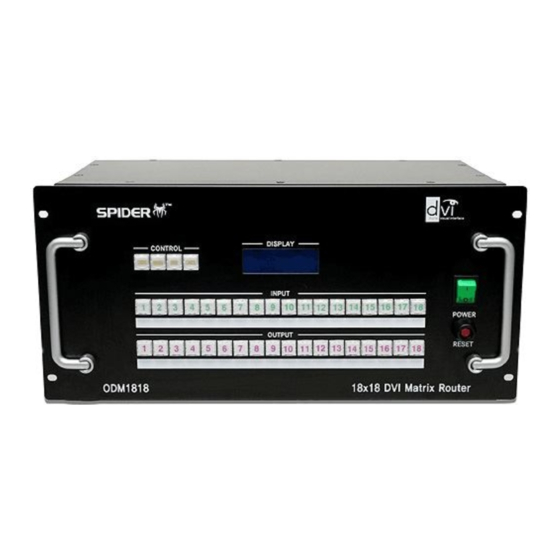
AND I NTRODUCTION NSTALLATION The ODM1818, 18X18 DVI Matrix Router is a high speed cross switcher of 18 DVI inputs and 18 DVI outputs. Having a ruggedized metallic enclosure, the ODM1818 gives applicability to harsh environments. The key features are;... -
Page 5: Notice For Safe Usage
The shipping group consists of the followings; Hard plastic case to carry: 1 set Mainframe of ODM1818: 1 set AC/DC power adaptor (12V/10A, AC110V-240V): 1 set AC power cord: 1 set User Manual: 1 set CD storing PC control software: 1 set A plug –... -
Page 6: Physical Description
1.2 Physical Description The ODM1818 is mountable on 19” standard rack with brockets. On front panel are some function keys, input-output buttons and a status display window placed as shown in Figure 1-1. CONTROL keys: ① Create - Start updating or configuring input-output setup Preview - Show current status of input-output configuration Cancel –... - Page 7 Eighteen (18) single link DVI inputs - female type: ① Eighteen (18) single link DVI outputs - female type: ② DIP switch - 8 bits to set identifier in case of multiple connection of ODM1818: ③ USB B type receptacle port: ④...
-
Page 8: Edid Control And Configuration
EDIDs to an EEPROM of each input by front key control, command codes and web control panel setting. The ODM1818 gives two choices for EDID setting out of fixed factory EDID and direct readout-store EDID of any targeted display. The factory default setting is UXGA (1,600x1,200) at 60Hz for all inputs. - Page 9 USER MODE on the display window, which means being ready to accept commands. RACK MOUNTING Before installing cables, the ODM1818 has to be mounted on the rack. On both front faces of the side chassis are two holes tapped to screw L-shape plates to the rack.
-
Page 10: Setting Router Id Of Odm1818
2.1 Setting Router ID of ODM1818 If you have multiple routers of ODM1818 with a video controller or PC for control, at first each ODM1818 should be identified with DIP switch setting, located on the rear panel marked in Router ID. -
Page 11: Preview Mode
Sequentially push another input button and match any outputs for the input until all inputs are configured. Pushing any of CREATE, PREVIEW or CANCEL shows the current configuration of in-out match. 2.2.2 PREVIEW Mode It shows configuration of in-out match. The PREVIEW button is toggled. Push the button to light in Orange and shows the in-out connection diagram on the display window. - Page 12 ◀ MONITOR MODE ▶ Input Channel : You could push any input buttons to be monitored among eighteen (18) input keys. Push ENTER button to finish the process. SETTING FOR COMMUNICATION MODE IP ADDRESS Select the mode for IP ADDRESS using Create & Function key. Input 17 and 18 buttons make the Under Bar move to left and right, respectively.
- Page 13 ◀ NETWORK INFO ▶ Subnet Mask: C : 255. 255. 255. 000. E : 255. 255. 255. 000. as a temporary and then 255. 255. 255. 000 is preset in factory. . Pressing PREVIEW button store finishes the process and back to the user mode by push the ENTER button. GATEWAY Select the mode for SUBNET MASK using Create &...
- Page 14 MAC ADDRESS Select the mode for MAC ADDRESS using Create & Function key. NUMBER 0 : INPUT 10 NUMBER 1 ~ 9 : INPUT 1 ~ 9 ASCII CHARACTOR A ~ F : INPUT 11 ~ 16 Input 17 and 18 buttons make the Under Bar move to left and right, respectively. ◀...
- Page 15 Select the mode for SETTING COMMAND TYPE using Create & Function key. NUMBER 1 ~ 3 : INPUT 1 ~ 3 COMMAND TYPE : 1. ODM1818 (RT CODE) 2. ODM1818 (DATA LENGTH 2BYTE OLD TYPE CODE) 3. ODM1818 (DATA LENGTH 3BYTE NEW TYPE CODE) ◀ Command Type ▶ Entry(1,2,3,4) :...
- Page 16 SETTING EDID AT INPUTS Select the mode for BAUD RATE TYPE using Create & Function key NUMBER 1 ~ 18 : OUTPUT 1 ~ 18 Page Move : INPUT 15, 16 Cursor move : INPUT 17, 18 Other Channel status : Using Page move key (Each page show the status of 6 channel) EDID control : Page key and cursor key make the under bar move to Edit window (Input &...
-
Page 17: Serial Communication
The ODM1818 provides a command line interface being executed through the serial port, RS-232C. Consider a PC running the Microsoft Windows operating system as a controller for ODM1818. The PC is provided with serial emulation software so called as HyperTerminal. ODM1818 supports communication with this software in an efficient way. - Page 18 Figure 2-2 Connection Description Dialog In the dialog, enter a name and choose an icon. Clicking OK displays the Connect To di- alog box. Figure 2-3 Connect To Dialog In the Connect To dialog box, ignore the Country, Area Code and Phone Number fields. In the Connect Using field, choose the available COM port to which the serial cable from 18/59...
- Page 19 Bits per second (baud rate): 19200 (recommended) or others Data bits: 8 Parity: None Stop bits: 1 Click OK to display the HyperTerminal window. Make sure that the communication of ODM1818 is ready by pressing ENTER. Send command set. (Refer to Chap. 3.2) 19/59...
- Page 20 2.3.2 Telnet Telnet is a user command and an underlying TCP/IP protocol for accessing remote computers. Through Telnet, an administrator or another user can access someone else's computer remotely. On the Web, HTTP and FTP protocols allow you to request specific files from remote computers, but not to actually be logged on as a user of that computer.
- Page 21 Click OK to open the Windows command window. At the prompt in the command window, type: telnet <ip_address> 8000 where <ip_address> stands for the IP address of the ODM1818. For example, if it keeps the default IP, type as follows; telnet 192.168.000.088 8000 ….
-
Page 22: Ethernet Control
Telnet session to a private port. To make ODM1818 connect through the Ethernet port, it should be set to have a unique, static IP address. The default IP from factory is 192.168.000.088. To acquire a valid IP in your LAN network, contact your network manager to avoid IP conflict. -
Page 23: Usb Control
Close all windows opened during this procedure. 2.5 USB CONTROL The control of ODM1818 through USB connection is only valid with the proprietary PC software, but not with command line interface. For its device installation and instruction to use, refer to the Proprietary PC Software Operation in Chap. -
Page 24: Front Panel Operation
RS 232C, Ethernet, or USB. All functions are executed in a basis of command line interface, but graphic interfaces on the WCP or the PC software make more efficient to operate the ODM1818. Firmware and PC software are managed according to versions in release or upgrades and are shown how to upgrade in the firmware and software management in Appendix B. - Page 25 4. Confirm the message to successfully execute storing the EDID as configured; Note that the stored EDID setting keeps until re-taking the EDID setting process, even though the ODM1818 is powered on and off repeatedly. 5. For the last step, input-output configuring, push CREATE key to display the existing in- put-output configuration below;...
- Page 26 window; ◀ Create Mode ▶ Input Channel : 7. Enter the number 1 and 4 as a selection of outputs for the given input and push ENTER key and then turn back to the user mode. Note that it is possible to select the output channels for any input as many as wished. 8.
-
Page 27: Command Line Operation
All strings starts with Start byte. To set Router ID, refer to 2.1 Setting Router ID of ODM1818 on page 10, to be selectable in a range of 000 to 255, written in 3 bytes. - Page 28 Selected Output Ch Input Ch Variable Selected Input Ch 0x21 Tail Code As a response of command line input to ODM1818, it returns any of the following ACK signals to the controller shown in Table 3.2 if it is not specified. 28/59...
- Page 29 Table 3.2 Description of Acknowledge(ACK) Signals Acronym Bytes ASCII Codes Description Error 0x05 Router received the irregular data packet RX Complete 0x06 Router received the regular data packet Job Complete 0x07 Completed the operation per command Connection OK 0xA0 Connection has been successfully done After sending command codes, ACK will be returned.
- Page 30 Ex. 4> Eighteen (18) channels direct –through connection Start Router ID Command Data Length Output ch Input ch ASCII Output Ch Input Ch … Output Ch Input Ch Output Ch Input Ch … PREVIEW COMMAND It shows configuration of all input-output match. Format of Command line: Start (*) + Router ID (3 byte) + Command (1) + Data Length (000) + End (!) Byte...
- Page 31 0x06(06h) + Connection DATA + 0x07(07h) The Connection Data represents the connection information of router 1) Connection Data of ODM1818 for a connection of 1-1, 2-2, 3-3 … … 16-16, 17-17, 18-18 Byte Start Router ID...
- Page 32 Output Ch Input Ch Output Ch Input Ch 2) Output Ch1 Input Ch2, Output Ch2 Input Ch3, Output Ch3 Input Ch1 Byte Start Router ID Command Data Length Output Ch Input Ch ASCII Output Ch Input Ch Output Ch Input Ch 3) Output Ch1 Input Ch3, Output Ch2 Input Ch1, Output Ch3 =>...
- Page 33 Start Router ID Command Data Length ASCII Sending Check Connection command to router let ODM1818 respond ACK signal to controller in a format as follows; Good connection: 0xA0 (A0h) Bad connection: 0x05 (05h) UPLOAD ONE CHANNEL DATA REQUEST It enables to upload the connection status of a selected input channel.
- Page 34 READ OUTPUT DEVICE EDID It enables to read EDID from connected display. Format of Command Line: Start (*) + Router ID (3 byte) + Command (A) + Data Length (002) + Output ch (2 byte) + End Ex.> Read EDID from a Display connected to Output 1 Byte Start Router ID...
- Page 35 Variable in Data Length is determined by multiplying 2 bytes to the maximum number of input channels. In case of ODM1818, it is 16 bytes, multiplying 2 bytes to 8 inputs. The 2 bytes in EEPROM # represents the output number connected to a targeted display, the EDID of which would be stored to the EEPROM #.
-
Page 36: Web Control Panel Operation
ASCII 3.3 Web Control Panel Operation The web control panel (WCP) gives a graphic alternative to command line interface. ODM1818 supports to be operated by a standard web browser. Microsoft Explorer is highly recommended to use. Before running the web browser, confirm that the set-up for Ethernet connection is pre-performed as guided in the …. -
Page 37: Proprietary Pc Software Operation
3.4 Proprietary PC Software Operation 3.4.1 Installation of PC Program Application Follow the instructions below to install the ODM1818 software into your PC. Insert the ODM1818 software CD into your PC. If the CD does not automatically run, click Start >Run. Enter X:\ ‘ODM1818-install.exe, where X is the letter of your CD drive. - Page 38 To terminate the installation Click the 'Ok' button. Click the 'Yes' button to update the registry. Click the 'Ok' button. 38/59...
-
Page 39: Installation Of Usb Driver
3.4.2 Installation of USB Driver Windows XP Please turn on the Router Power after connecting PC and the Router over USB cable. Please push the "NEXT" button after checking the option button as shown below. Insert enclosed CD into the CD-ROM and select the searching Location and click the "NEXT" button as shown below. - Page 40 Please complete the installation by clicking the "FINISH" button. 40/59...
-
Page 41: Operation By Pc Program
3.4.3 Operation by PC program 1) Initialize the PC program. - Check the communication cable (RS-232C, LAN or USB) and turn on the router. - Double click the PC program. - Set the same Router ID number on the PC program as the DIP switch setting on the rear panel of router. - Page 42 2) Control Buttons 1) Cre (Creat) Function: It has the same function as the Create-Button on the router front panel. It setups the Input-Output channel connection. Process: Cre. Button Input Button Output Button Ent. Button 2) Pre (Preview) Function: It has the same function as the Preview-Button on the router front panel. It checks the current Input-Output connection states.
- Page 43 It downloads current input-output channels pattern to router. 3 Upload Pattern from Device It uploads current input-output channels pattern to PC program. 4 Exit It terminates the application program, ODM1818. 4) Edit Pattern a) Edit: It modifies the current input-output switching pattern. - Click the edit button.
- Page 44 - User can check the switching-pattern database at program folder (c:\program files\ ODM1818). b) Add - Set the pattern name as (My_Grace) and than push the Add button on the PC program. - Once this is done, user can see the new switching-pattern as below.
- Page 45 - Click the edit button then user can edit switching-pattern and input-output names. c) Modify - Select the switching-pattern, to be modified. - Write down the new pattern name in the combo box. - Click the Modify button. - It is almost same as ‘SAVE AS’ in window program. d) Delete - Select the pattern name, to be deleted.
- Page 46 For example, if the current switching-pattern is same as step 1 as below and want to rotate the input channels on output 1, 2, 3, 4, 5. Please check the rolling box 1, 2, 3, 4, 5 and set the interval you want.
- Page 47 6) EDID Setting It provides several EDID handling function Store EDID Read EDID from output device Read EDID from output device and store it in input EEPROM EDIT user defined EDID Restore default EDID (in all input channel) One touch storing (in all input channel) Storing EDID by individual selection Basic EDID structure: EDID Block 0 [128 bytes] But, the most useful and important methods are described here.
-
Page 48: Trouble Shooting
Check the power cord is correctly connected to the Power No Power LED ODM1818 and to an AC power source and that the power switch is in the ON position Check the input output DVI cables are correctly connected to each port of ODM1818 and double check the input output connection configuration you want. -
Page 49: Specification
7) Fulfill real-time display of running status on 20x4 LCD and with illuminated LED type keys. 8) Be rack-mountable with solid 19 inch standard RACK TYPE CASE (3U). 9) Support real-time Hot_Plug Detection and program each EDID to connected DVI sources as per user’s specification. -
Page 50: Firmware Downloading
1. Installation of the Ponyprog2000 Follow the instructions below to install the PonyProg2000 software into your PC. Insert the ODM1818 software CD into your PC. Go to Downloader directory in CD and execute setup.exe. The following screen will open. Then, click NEXT button. - Page 51 Define destination directory and click ‘Next’ button. Select Start Menu Folder as below. 51/59...
- Page 52 Click ‘Install’ button to install the software in your PC Click ‘Finish’ then PonyProg2000 will be installed in your PC successfully. 52/59...
- Page 53 2. Download of Firmware Turn on Router and connect Router (to Download port) and PC( to Parallel port) over firmware download cable. Execute PonyProg2000.exe and click ‘OK’. Click ‘OK’ button for calibration. 53/59...
- Page 54 Select ‘AVR micro’ as below. Select ‘Atmega128’ as below. 54/59...
- Page 55 Select ‘Interface Setup’ in Setup menu as below. Set I/O port as below and click ‘OK’ button 55/59...
- Page 56 Select ‘Security and Configuration Bits’ in Command menu. Click the ‘Read’ button and make sure option is set as below. If the option is not same as below click the ‘Clear All’ to reset and check it again. Then click ‘Write’ button and click ‘Read’ button and check the option is same and below again. 56/59...
- Page 57 Select ‘Open Program (FLASH) File’ in File menu and select new firmware to download. Select ‘Write Program(FLASH)’ in Command menu. 57/59...
- Page 58 Click ‘OK’ button then it starts downloading and verifying continuously. Click ‘OK’ to terminate the downloadin. Now the Router is operated under the new firmware. 58/59...
- Page 59 Opticis Locations Opticis Co., Ltd. Opticis North America Ltd. #501 Byucksan Technopia, 434-6, 330 Richmond Street, Suite 100, Sangdaewon-Dong, Chatham, Ontario, Canada N7M 1P7 Chungwon-Ku, Sungnam City, Tel: (519) 355-0819 Kyungki-Do, 462-120, South Korea Fax: (519) 355-0520 Tel: +82 (31) 737-8033 Fax: +82 (31) 737-8079 For order support, please contact your Distributor or Reseller.
Need help?
Do you have a question about the ODM1818 and is the answer not in the manual?
Questions and answers