
Summary of Contents for Tait Scape
- Page 1 Scape I N S T A L L A T I O N G U I D E Tait’s original designs are protected under intellectual property law V . 3 . 2 0 2 1...
-
Page 2: Table Of Contents
Contents Prior to Installation ..................................Tools & Equipment ..................................Specifications ....................................Scape Modules & Components - Plan View ......................Levelling Base - Free Standing Installation ......................Levelling Base - Fixed Installation ..........................Side Table & Canopy - Installation ..........................Backrest - Installation ................................ -
Page 3: Prior To Installation
• Tait’s Scape modules are built to be strong, durable, and last for many years. However, placing the modules on un-level ground can create leveraging stresses that can cause cracking and even breakage that is not covered in the product warranty. -
Page 4: Tools & Equipment
Tools & Equipment T O O L S A N D E Q U I P M E N T S U P P L I E D Weights (if weighted installation is specified) Drainage riser (if specified) T O O L S A N D E Q U I P M E N T R E Q U I R E D Drill 17mm spanner No. -
Page 5: Scape Modules & Components Plan View
Scape Modules & Components Plan View M O D U L E M0 = Module Side Table location L O N G M O D U L E Canopy available on all LM0, LM1, LM2 = Long Module Side Table location options... -
Page 6: Levelling Base - Free Standing Installation
If weights are to be added, place the weights in the module in the below configuration. Tait recommends the use of DEKO 250 x 150 x 150mm Instant Concrete Foundation Block (13kg each). The blocks should be stacked in pairs as shown above to increase stability Four pairs of blocks are to be placed in the Module and 8 pairs of blocks are to be placed in the Long Module. -
Page 7: Levelling Base - Fixed Installation
Levelling Base F I X E D I N S T A L L A T I O N Prior to fixing any components, check the GRC base is sitting level with the ground. Remove existing levelling feet and if GRC base is not level, use levelling packers under the GRC feet to correct. Fixing to be M12 bolt with minimum length of 150mm, topped with an M12 mudguard washer. -
Page 8: Side Table & Canopy - Installation
I N S T A L L A T I O N Side Table and Canopy are suited to all Scape Modules. The installation for the Side Table and Canopy are identical. Please cross-check the sales order to confirm you have the correct part, location and colour for the specified configuration. - Page 9 Check level of the Side Table/Canopy and once satisfied, fully tighten the nuts The tubes should meet flush to the GRC base and the components should be firmly in place CAUTION: SCAPE MODULES AND LONG MODULES WITH SIDE TABLE AND CANOPIES INSTALLED MUST HAVE FIXED OR WEIGHTED INSTALLATION.
-
Page 10: Backrest - Installation
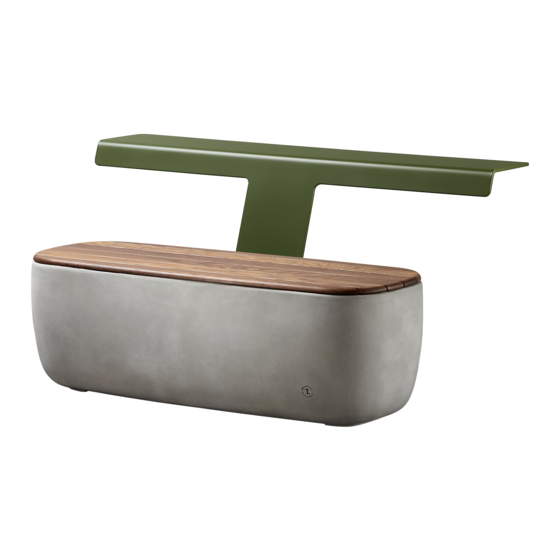
I N S T A L L A T I O N Backrest is suited to Scape Module and Long Module Only. Backrest requires two persons for installation. Backrests are available in both left and right orientations. Please cross-check the sales order to confirm you have the correct part, location and colour for the specified configuration. - Page 11 I N S T A L L A T I O N Table is suited to Scape Module only. Table component requires two persons for installation. Please check the sales order to confirm you have the correct part, location and colour for the specified configuration.
- Page 12 Table I N S T A L L A T I O N C O N T I N U E D No. 17 Check level of the table and once satisfied, fully Finger tighten the nuts using a spanner tighten the nuts CAUTION: NEVER LEAN AGAINST PRODUCT DURING INSTALLATION AS PRODUCTS MAY TOPPLE OVER.
- Page 13 Table C O N F I G U R A T I O N 1 This configuration must to be fixed to the ground. Please refer to ‘Levelling Base - Fixed’ on page 7 of this guide. CAUTION: NEVER LEAN AGAINST PRODUCT DURING INSTALLATION AS PRODUCTS MAY TOPPLE OVER.
- Page 14 Table C O N F I G U R A T I O N 2 No. 17 × 2 Straight Brackets Place the straight brackets aligned with the holes in the table as shown above, and insert the M8 bolts. Tighten the bolts using the 5mm T-bar Allen key.
- Page 15 Table C O N F I G U R A T I O N 3 This configuration must to be fixed to the ground. Please refer to ‘Levelling Base - Fixed Installation’ on page 7 of this guide × 1 ‘C’ Bracket Place the ‘C‘...
- Page 16 Table C O N F I G U R A T I O N 4 × 2 Straight Brackets Place the straight brackets aligned with the holes in the table as shown above, and insert the M8 bolts. Tighten the bolts using the 5mm T-bar Allen key.
- Page 17 Table C O N F I G U R A T I O N 4 C O N T I N U E D × 1 ‘H’ Bracket Place the ‘H‘ centre bracket aligned with the holes in the table as shown above, and insert the M8 bolts. Tighten the bolts using the 5mm T-bar Allen key.
-
Page 18: Scape Island With Planter - Drainage Riser
D R A I N A G E R I S E R Scape Island with Planter Only: Where drainage risers are specified for planting section, apply silicone around base of drainage riser and place into drainage hole ensuring a water proof seal has been created. -
Page 19: Fixing Seat To Grc Base - Installation
Fixing GRC Seat to GRC base I N S T A L L A T I O N Take the correct GRC seat making sure there is foam padding applied on the underside. With assistance, place the seat on the base, be careful to prevent your fingers being pinched in between the two parts. - Page 20 Once happy with placement firmly apply pressure to ensure a strong bond. CAUTION: DOUBLE-CHECK ALL COMPONENTS AND FIXINGS ARE LOCATED IN CORRECT POSITION AND FASTENED CORRECTLY BEFORE SEALING SEAT TO GRC BASE. This assembly method applies to the timber seats for the Scape Module and Long Module.
-
Page 21: Delivery & Installation Requirements
Delivery & Installation Requirements Thank you for considering Scape in your next project. To provide you with an accurate Scape quotation as well as delivery and installation support relevant to your project needs, Tait require this document to be completed and authorised by relevant person/s. - Page 22 Y/N PLEASE NOTE: If flooring surface is found to be uneven, your Scape warranty may be void. CUSTOMER SITE READINESS REQUIREMENTS Tait will contact the client on order completion to reconfirm the above details. ITEM UNDERSTOOD (PLEASE TICK)
Need help?
Do you have a question about the Scape and is the answer not in the manual?
Questions and answers