
Related Manuals for MaxLinear XR77103-A1R0

Summary of Contents for MaxLinear XR77103-A1R0
- Page 1 XR77103-A1R0 Universal PMIC 3 Output Buck Regulator EVB User Manual MaxLinear Confidential • www.maxlinear.com • 010-A1R0UMR00 TBD/18 010-A1R0UMR00...
- Page 2 XR77103-A1R0 Universal PMIC 3 Output Buck Regulator EVB User Manual Revision History Revision History Document No. Release Date Change Description 010-A1R0UMR00 March 10, 2022 Updated: ■ "Quick Set Up - Factory Settings" section. ■ "Simplified Block Diagram, XR77103-A1R0 EVB" figure.
-
Page 3: Table Of Contents
XR77103-A1R0 Universal PMIC 3 Output Buck Regulator EVB User Manual Table of Contents Table of Contents Introduction...................................1 Quick EVB Set Up and Start Up ............................1 Factory Settings ..............................1 Quick Start Up ..............................1 Reference Documentation ..............................3 Ordering Information................................3 Evaluation Board Overview ..............................4 I/O and Test Points ................................4... - Page 4 XR77103-A1R0 Universal PMIC 3 Output Buck Regulator EVB User Manual List of Figures List of Figures Figure 1: Connecting and Monitoring V and V .......................2 Figure 2: Top View of XR77103-A1R0, REV2.0........................3 Figure 3: Simplified Block Diagram, XR77103-A1R0 EVB .....................4 Figure 4: XR77103EVB-A1R0 Schematic ..........................7...
- Page 5 XR77103-A1R0 Universal PMIC 3 Output Buck Regulator EVB User Manual List of Tables List of Tables Table 1: Jumper Connections for V and PGND ......................1 Table 2: Evaluation Board Ordering Part Number........................3 Table 3: Test Points................................4 Table 4: Factory Settings................................5 Table 5: Jumper J3 Options for the EN Pin ..........................5...
-
Page 6: Introduction
The XR77103-A1R0 evaluation board provides a platform to evaluate the features and performance of the XR77103-A1R0 Universal PMIC 3 Output Buck Regulator. The XR77103-A1R0 output voltages are set via an external resistor divider down to 0.8V with a 4.5V to 14V input voltage range, and it is packaged in a 4mm x 4mm TQFN. -
Page 7: Figure 1: Connecting And Monitoring Vin
XR77103-A1R0 Universal PMIC 3 Output Buck Regulator EVB User Manual Quick EVB Set Up and Start Up VIN+ VIN- Figure 1: Connecting and Monitoring V and V March 10, 2022 010-A1R0UMR00... -
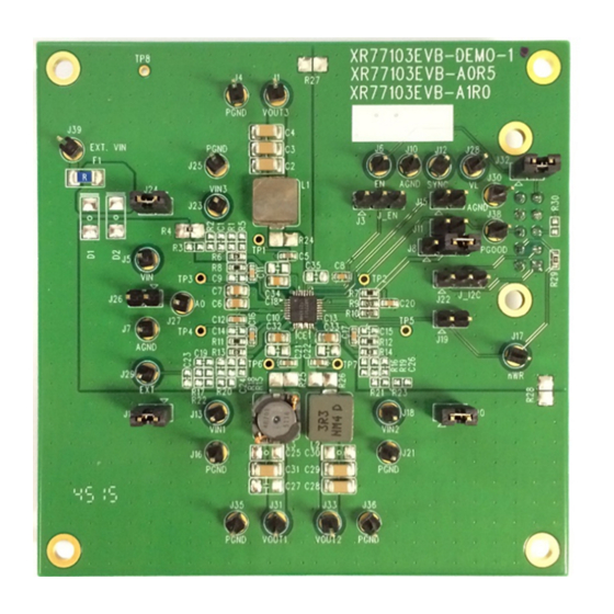
Page 8: Reference Documentation
XR77103-A1R0 Universal PMIC 3 Output Buck Regulator EVB User Manual Reference Documentation Figure 2: Top View of XR77103-A1R0, REV2.0 Reference Documentation For additional information, refer to the XR77103-A1R0 data This manual provides the EVB schematics (“XR77103EVB- sheet, including a full list of IC features, pinout, pin A1R0 Schematic”... -
Page 9: Evaluation Board Overview
XR77103-A1R0 Universal PMIC 3 Output Buck Regulator EVB User Manual Evaluation Board Overview Evaluation Board Overview The XR77103-A1R0 EVB block diagram is shown in Figure OUT1 OUT2 XR77103-A1R0 OUT3 PGOOD J15 (SYNC) Figure 3: Simplified Block Diagram, XR77103-A1R0 EVB I/O and Test Points... -
Page 10: System Set-Up
XR77103-A1R0 Universal PMIC 3 Output Buck Regulator EVB User Manual System Set-Up System Set-Up Table 4 lists a summary of the jumpers and factory settings to configure the EVB for operation. For additional information, refer to the XR77103-A1R0 data sheet. -
Page 11: Table 7: Jumper J11 And Operation From A 5V Rail
XR77103-A1R0 Universal PMIC 3 Output Buck Regulator EVB User Manual Jumper J11 Table 7: Jumper J11 and Operation from a 5V Rail Jumper Options Description Jumper 1-2 which is required for 5V operation. Ties the LDO output to No jumper (default) -
Page 12: Xr77103Evb-A1R0 Schematic
XR77103-A1R0 Universal PMIC 3 Output Buck Regulator EVB User Manual XR77103EVB-A1R0 Schematic XR77103EVB-A1R0 Schematic 3.5A FUSE VIN_EXTERNAL VOUT3 3.3uH VOUT3 22uF 47nF PGND 4.7uF 4.7uF PGOOD VIN3 J_PGOOD VIN_EXTERNAL Jumper AGND VIN1 Jumper J_EN ICE1 VOUT3 VIN1 4.7uF VOUT3 PGOOD... -
Page 13: Xr77103Evb-A1R0 Pcb Layers
XR77103-A1R0 Universal PMIC 3 Output Buck Regulator EVB User Manual XR77103EVB-A1R0 PCB Layers XR77103EVB-A1R0 PCB Layers Figure 5: Silkscreen Top Figure 6: Assembly Top/Layer 1 Figure 7: Layer 2 Figure 8: Layer 3 March 10, 2022 010-A1R0UMR00... -
Page 14: Figure 9: Assembly Bottom
XR77103-A1R0 Universal PMIC 3 Output Buck Regulator EVB User Manual XR77103EVB-A1R0 PCB Layers Figure 9: Assembly Bottom March 10, 2022 010-A1R0UMR00... -
Page 15: Xr77103Evb-A1R0 Bill Of Materials
XR77103-A1R0 Universal PMIC 3 Output Buck Regulator EVB User Manual XR77103EVB-A1R0 Bill of Materials XR77103EVB-A1R0 Bill of Materials Table 8: XR77103EVB-A1R0 Bill of Materials Manufacturer/ Package Item Reference Designator Component Part Number Size XR77103 Evaluation Board MaxLinear C3, C27, C29, C31... - Page 16 Products are not authorized for use in such applications unless MaxLinear, Inc. receives, in writing, assurances to its satisfaction that: (a) the risk of injury or damage has been minimized; (b) the user assumes all such risks; (c) potential liability of MaxLinear, Inc.
Need help?
Do you have a question about the XR77103-A1R0 and is the answer not in the manual?
Questions and answers