Advertisement
Advertisement
Table of Contents

Summary of Contents for YOSE POWER DZ40
- Page 1 DZ40 display Specification Manual Product Name: LCD Display Product Model: DZ40...
- Page 2 Catalogue 1.Product introduction 1.1 product introduction 1.2 product introduction 1.3 Scope of use 1.4 Appearance and size 1.5 Display coding rules 2.Product description 2.1 Specification parameters 2.2 Function overview 2.3 Installation method 2.4 Display interface 2.4.1 Turn on interface 2.4.2 Riding interface 2.5 Key definition 2.6 Function operation 2.6.1 On/Off...
-
Page 3: Product Introduction
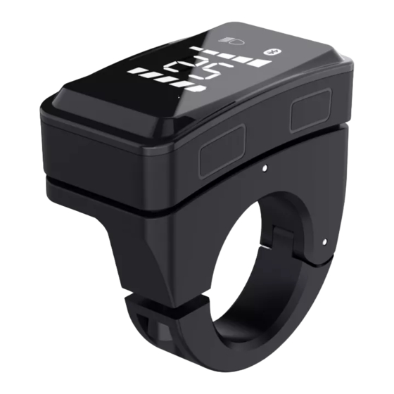
1. product introduction 1.1 product name and model LCD Display, model: DZ40 1.2 product introduction Simple and thin, installed on the left, can be used with the middle display; High brightness white nixie tube; Waterproof lever: IP65; UART communication interface is convenient for maintenance service 1.3 Scope of use... -
Page 4: Product Description
1.5 Display coding rules SW102 product model (this information is not included in bar-code information); C-manufacturer code or production team code; S2-product model code; C01-indicates the number of weeks in the production year; B-indicates the hardware version; 101-indicates the firmware version number; 0001-indicates the serial number of the product. -
Page 5: Installation Method
2.3 Installation method ① Open the display locking clip, cover it on the left handlebar (standard handle pipe size: φ 22.2), adjust it to an easy-to-operate position, fix it with M3 inner hexagon and tighten the fixing screw. The locking torque is 0.8N.m. * display damage caused by excessive torque is not covered by warranty. -
Page 6: Key Definition
2.5 Key definition Switch on/off: function key: adjustment key+:upper part of display display area (explained by ), adjustment key-:lower part of display display area (explained by 2.6 Function operation 2.6.1 On/Off Keep the normal connection state between the display and the controller, press the key for 2 seconds when the display is turned off, and the display will fully display the startup interface, then enter the basic interface normally and start working;... -
Page 7: User Settings
Turn off the lights (high brightness) and turn on the lights (low brightness) 2.6.5 Electricity display When the battery power is normal, the battery 5-segment LCD displays the power according to time and the outer frame lights up. When the battery is exhausted, the 5-segment LCD of the battery is completely extinguished and the outer frame flashes, so it needs to be charged immediately. - Page 8 2.7.1 Enter Settings Within 10 seconds of starting up, press and hold the (2 seconds), and the system will enter the user setting interface. In this state, relevant parameters can be set and viewed. Long press the (2 seconds) to exit and save the setting status. When the user sets the interface state, if it is not operated for 10 seconds, the display will return to the normal riding state without saving the parameter settings.
- Page 9 26inch 700C 2.7.4 Speed limit information After entering the setting interface, press briefly to switch the setting content to enter the wheel diameter information (the third section of the gear flashes and the fifth end is always on). You can view the speed limit information (the default speed limit is 25km/h).
-
Page 10: Fault Information
The voltage is 36V 2.8 fault information 2.8.1 Fault display The fault icon and fault code are displayed, and the fault code flashes. 2.8.2 Definition of Fault Code The fault code is obtained from the controller instruction. Generally, the controller defines the meaning of error codes. - Page 11 2.9 Wiring definition Display outlet terminal Connector connect to the controller Table 1 Standard connector wiring definition table Standard line Standard line color function sequence Red (VCC) display power cord Power control line of controller Blue (Kp) Black (GND) display ground wire Green (RX) Data receiving line of display Yellow (TX)
Need help?
Do you have a question about the DZ40 and is the answer not in the manual?
Questions and answers