Table of Contents
Advertisement
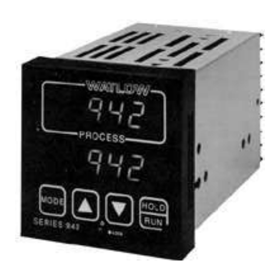
Series 942
User's Manual
Microprocessor-Based
Ramping Control
W a t l o w C o n t r o l s
W a t l o w C o n t r o l s
W a t l o w C o n t r o l s
W a t l o w C o n t r o l s
W a t l o w C o n t r o l s
1241 Bundy Blvd., P.O. Box 5580, Winona, MN 55987-5580, Phone: 507/454-5300, Fax: 507/452-4507
W942-XUMN Rev. R00
June, 1995
Supersedes:
W942-MA40-9305
1/4 DIN
TOTAL
CUSTOMER
C U S T O M E R
S A T I S F A C T I O N
SATISFACTION
$10.00
Made in the U.S.A.
Printed on Recycled Paper
Advertisement
Table of Contents

Related Manuals for Watlow 942 Series

Summary of Contents for Watlow 942 Series
- Page 1 Series 942 User's Manual TOTAL CUSTOMER C U S T O M E R S A T I S F A C T I O N SATISFACTION 1/4 DIN Microprocessor-Based Ramping Control W a t l o w C o n t r o l s W a t l o w C o n t r o l s W a t l o w C o n t r o l s W a t l o w C o n t r o l s...
- Page 2 WATLOW Series 985 User's Manual Appendix...
-
Page 3: Table Of Contents
Contents Page Item Chapter 1 Starting Out With The Watlow Series 942- General Description Opening the 942 Figures, Tables, Charts Set the DIP Switches Page Item Figure Series 942 Input & Output Overview Chapter 2 How to Open the Series 942... - Page 4 Select either retransmit of process variable or set point. Operator-friendly features include automatic LED indicators to aid in monitoring and setup, as well as a calibration offset at the front panel. The Watlow Series 942 automatically stores all information in a non-volatile memory.
-
Page 5: Dip Switch Location And Orientation
This insures proper electrical contact. How to Set the DIP Switches The Watlow Series 942 has a Dual In-line Package (DIP) switch inside the control on the A007-1954 circuit board (middle board). The location of the board and switch appear below. -
Page 6: How To Install And Wire The Series 942
This chapter tells you how to install the Series 942. All mounting and wiring information is right here. Because Watlow controls are thoroughly tested and "burned in" before leaving the factory, the Series 942 is ready to install when you receive it. -
Page 7: Series 942 Panel Cutout Dimensions
3.625 x 3.625 (92.00 to 92.79mm 0.06" to 0.25" (92.08 X 92.08 mm) 0.06 to 0.25 (92.08 x 92.08mm) (1.52 to 6.35mm) (1.524 to 6.35mm) Nominal NOTE: All dimensions in inches. Install and Wire, Chapter 2 WATLOW Series 942 User's Manual... -
Page 8: Sensor Installation Guidelines
Put the sensor as near as possible to the material or space you want to control. The sensor should be thermally insulated from the sensor mounting. WATLOW Series 942 User's Manual Install and Wire, Chapter 2... -
Page 9: Input Wiring
To overcome this problem, use a three wire RTD sensor, which compensates for lead length resistance. When extension wire is used for a three wire RTD, all three extension wires must have the same electrical resistance. (i.e. same gauge, copper stranded). Install and Wire, Chapter 2 WATLOW Series 942 User's Manual... - Page 10 A jumper must be 4 - 20mA Process installed between Input Wiring. Terminals #2 and 3. NOTE: When using a 4 - 20mA process input, the input impedance is 249 Ω WATLOW Series 942 User's Manual Install and Wire, Chapter 2...
-
Page 11: Output 1 Wiring
Switch Switched DC Watlow's solid state switch is a low current DC output (open collector) used to switch an external power switching device such as an SSR or an electromechanical relay. The input specifications of the power switching device must match those listed for the SS switch output. - Page 12 Proportional value determined by the control to balance the sensor input and set point. This value will fall between 0 - 10VDC depending on the thermal characteristics of the system. Load impedance is 10K Ω minimum. WATLOW Series 942 User's Manual Install and Wire, Chapter 2...
- Page 13 Proportional value determined by the control to balance the sensor input and set point. This value will fall between 0 - 20mA depending on the thermal characteristics of the system. Load impedance is 600 Ω maximum. Install and Wire, Chapter 2 WATLOW Series 942 User's Manual...
- Page 14 Fuse Solid State Relay Without Contact Suppression Watlow's solid state relay changes state at zero volts, which is "zero-cross switching." They are also optically isolated, which means the output circuitry is energized by infrared light striking a photosensitive device. This results in a virtual absence of electrically generated noise, plus output to input electrical isolation.
-
Page 15: Output 2 Wiring
Output 2 Wiring. Switched DC Watlow's solid state switch is a low current DC output (open collector) used to switch an external power switching device such as a SSR or an electromechanical relay. The input specifications of the power switching device must match those listed for the S.S. switch output. - Page 16 Load Solid State Relay Without Contact Suppression Watlow's solid state relays change state at zero volts, which is "zero-cross switching." They are also optically isolated, which means the output circuitry is energized by infrared light striking a photosensitive device. This results in virtual absence of electrically generated noise, while providing output to input electrical isolation.
-
Page 17: Auxiliary Wiring
Model # 942A- _ _ _ - _ 000 Mechanical Relay, Form A or B, 6 Amp Figure 25 - Fuse Auxiliary Option 2 Wiring. Output #4 Load Fuse Output #3 Load Install and Wire, Chapter 2 WATLOW Series 942 User's Manual... - Page 18 Process, 4-20 mA, Non-Isolated Mechanical Relay, Form A or B, 6 Amp Figure 27 - Auxiliary Option 4 External Wiring. Load Output #4 Fuse Output #3 Load Load impedance 600 Ω maximum. WATLOW Series 942 User's Manual Install and Wire, Chapter 2...
- Page 19 4 - 20mA Retransmit, Auxiliary Output Model # 942A- _ _ _ - _ 000 Figure 29 - Auxiliary Option 6 Process, 4-20 mA, Non-Isolated Wiring. External Load Load impedance 600 Ω maximum Install and Wire, Chapter 2 WATLOW Series 942 User's Manual...
-
Page 20: System Wiring Example
Failure to observe NEC safety guidelines could result in injury to personnel. Figure 30 - System Wiring Example WARNING: Watlow mercury relays are designed to be used only with resistive loads. 945A-2DD0-A000 942A-1DD0-A000 945A-2DD0-A000 942A-1DD0-A000 Temperature Control... -
Page 21: How To Use The Keys And Displays
When blinking, press the Secures or releases the cally enters data changes before HOLD/RUN key again to begin control chassis from its case. proceeding to the next parameter. RUNning. Keys and Displays, Chapter 3 WATLOW Series 942 User's Manual... -
Page 22: How To Setup The Series 942
Protocol type Prot Alarm 1 ramge of the set Addr Address LAt1 Latching for alarm 1 point. Logging printout HYS3 Hysteresis 3 Time interval Silence alarm Variables to transmit Setup, Chapter 4 WATLOW Series 942 User's Manual... -
Page 23: Setup Parameters
High (rH) for process inputs and outputs. Process inputs and outputs are linearly scaled between rL and rH. Changing this parameter erases all profile steps and defaults them to an End step. Range: Sensor range high to rL Default: High limit of sensor type Setup, Chapter 4 WATLOW Series 942 User's Manual... - Page 24 SIL: Selects alarm silencing (inhibit) for Output 3. This parameter only appears when AL1 = dE, and Ot3 = AL. For more information see Chapter 6. Range: On or OFF Default: OFF Setup, Chapter 4 WATLOW Series 942 User's Manual...
- Page 25 Pout and the current parameter. rSET (Reset) causes a start from the beginning of your profile. Press the HOLD/RUN key to clear. Range: Cont (Continue), HOLd, Abrt (Abort), rSET (Reset) Default: Cont Setup, Chapter 4 WATLOW Series 942 User's Manual...
-
Page 26: Input Ranges
Range is at 32° to 32°F/0°C 2642°F/1450°C allow using at low *32°F/0°C 3092°F/1700°C temperatures (1°) -328°F/-200°C 1112°F/600°C without range low rt.d (0.1°) -99.9°F/-99.9°C 392.0°F/200.0°C sensor errors. 0-5 (VDC) -5.00/-50.0/-500 35.00/350.0/3500 420 (mA) -5.00/-50.0/-500 35.00/350.0/3500 Setup, Chapter 4 WATLOW Series 942 User's Manual... - Page 27 FULL or On FULL Addr 0 to 31 On or OFF 0.0 to 60.0 minutes PSA, PS-, P-A, P--, -SA, -S-, --A, --- P = Process, S = Set point A = Auxiliary Status Setup, Chapter 4 WATLOW Series 942 User's Manual...
-
Page 28: The Operation Menu
Only appears if Ot3 = Ent, and your unit has auxiliary outputs. For more information on events see Chapter 6. Range: On or OFF Default: OFF Setup, Chapter 4 WATLOW Series 942 User's Manual... - Page 29 1. This parameter only appears if you have an auxiliary output and Ot3 = AL. See the model number. If AL 1 = Pr: Range: rL to A1HI Default: rL If AL 1 = dE: Range: 0 to -999°F/0 to -999°C/0 to -999 Units Default: -999°F Setup, Chapter 4 WATLOW Series 942 User's Manual...
- Page 30 Appears if auxiliary output and Ot4 = AL. A2HI- Deviation dE 0° to 999° 999° Process Pr A2LO to rH Appears if auxiliary output and Ot4 = AL. ± 99°F/± 55°C/± 99 Units 0 to 3 Setup, Chapter 4 WATLOW Series 942 User's Manual...
-
Page 31: Program Menu
Jump step End Program HOUr Minute HOUr Return Hour Jump count Minute Return Second Event 1 Second Ent1 Rate Event 2 rAtE Ent2 Ent1 Return Event 1 Ent2 Event 2 (nO) Return (YES) Programming, Chapter 5 WATLOW Series 942 User's Manual... -
Page 32: Program Parameters
Return: Select no and you return to the StEP parameter to continue programming. By selecting YES, you exit the program menu and return to the control set point. Range: YES or no Default: no Programming, Chapter 5 WATLOW Series 942 User's Manaul... -
Page 33: Jumploops
Return: Select no and you return to the StEP parameter to continue programming the 942. By selecting YES, you exit the program menu and return to the control set point. Range: YES or no Default: no Programming, Chapter 5 WATLOW Series 942 User's Manual... -
Page 34: Resume A Profile
These End Set Point EnSP parameters are Hour remaining HOUr dependent on how your control is Minutes remaining configured. Seconds remaining rAtE Rate Event 1 Ent1 Event 2 Ent2 Elapsed jump count Programming, Chapter 5 WATLOW Series 942 User's Manaul... - Page 35 Events √ StPt HOUr Ent1 Ent2 rAtE SoAh HOUr Ent1 Ent2 OFFA HOLd Step # Step Type Values Time Events √ StPt HOUr Ent1 Ent2 rAtE SoAh HOUr Ent1 Ent2 OFFA HOLd Programming, Chapter 5 WATLOW Series 942 User's Manual...
-
Page 36: Event Outputs
Programmed in degrees or units, gSd is located in the Setup menu. Entering a value of (0) disables the Guaranteed Soak Deviation function. Programming, Chapter 5 WATLOW Series 942 User's Manaul... -
Page 37: Multiple Profiles
JC - 01 Step 6 Your Jump Count (JC) can be anything from 0 - 100. If you enter 0, this will be an infinite loop and never progresses to Step 6. Programming, Chapter 5 WATLOW Series 942 User's Manual... -
Page 38: Programming A Ramping Profile
2. The RUN LED begins flashing. The upper display shows the step to begin on, and the bottom display shows the StEP parameter. 3. Press the HOLD/RUN key again. If not pressed within approximately 1 minute, the RUN procedure will abort. The profile starts running. Programming, Chapter 5 WATLOW Series 942 User's Manual... -
Page 39: Editing Your Profile
Ot4 are selected set point. as alarms, the Temp/°F Step 1 Initializes Ent1 and Ent2 Edit Program Set Point. parameters will not appear in the Program menu. 10 20 100... Time (seconds) Programming, Chapter 5 WATLOW Series 942 User's Manual... -
Page 40: How To Tune And Operate
To abort auto-tuning, reset the AUt parameter to 0, or cycle power off and on. In all cases, aborting auto-tune restores all original values. Tuning and Operating, Chapter 6 WATLOW Series 942 User's Manual... - Page 41 Upper display. Then enter the CAL offset value you want. Calibration offset adds or subtracts degrees from the value of the input signal. Tuning and Operating, Chapter 6 WATLOW Series 942 User's Manual...
-
Page 42: Using Alarms
The Series 942 has two alarm types, Process or Deviation. A Process alarm sets an absolute temperature. When the process exceeds that absolute temperature limit an alarm occurs. The Process alarm set points may be independ- ently set high and low. Tuning and Operating, Chapter 6 WATLOW Series 942 User's Manual... -
Page 43: Deviation Alarm Example
Calibration or value is within the safe region of the deviation band. Any future deviation outside Setup Menus. this safe band triggers an alarm. Tuning and Operating, Chapter 6 WATLOW Series 942 User's Manual... -
Page 44: Error Code Display Example
Check the sensor; if the connection is good, and the sensor functions properly, call the factory. The A/D underrange voltage is too high to convert an A/D signal. Make sure the In parameter matches your sensor. Tuning and Operating, Chapter 6 WATLOW Series 942 User's Manual... - Page 45 • The above conditions will occur regardless of the value of LOC, or the presence of the Setup or Calibration Menus. • To clear a corrected error… • Cycle power to the control. Tuning and Operating, Chapter 6 WATLOW Series 942 User's Manual...
- Page 46 Switched DC Open collector, 500Ω minimum load resistance, 1KΩ load, 9mA minimum, 22mA maximum, non-isolated. • 0-20mA or 4-20mA reverse or direct into a 600Ω maximum load impedance, non-isolated. • 0-10VDC or 0-5VDC reverse or direct into a 1KΩ minimum load impedance, non-isolated. WATLOW Series 942 User's Manual Appendix...
- Page 47 • Height: 3.8 in 97 mm • Width: 3.8 in 97 mm • Overall depth: 7.0 in 178 mm • Behind panel depth: 6.0 in 153 mm • Weight: 2.5 lb max. 0.4 kg Appendix WATLOW Series 942 User's Manual...
- Page 48 Dual, Mechanical Relay, 6A, Form A or B Single, Mechanical Relay, 6A/0 - 5VDC retransmit Single, Mechanical Relay, 6A/4 - 20mA retransmit No auxiliary output/0 - 5VDC retransmit No auxiliary output/4 - 20mA retransmit Communications None Isolated RS-423/RS-422 Isolated EIA-485 WATLOW Series 942 User's Manual Appendix...
-
Page 49: Installation Guidelines For Preventing Noise
(sensor lines). A 12" (305 mm) minimum separation is usually effec- tive. Keep all switched output signal lines (high power level) separate from input signal lines (sensor lines). Cross other wiring at 90° angles whenever crossing lines is unavoidable. Appendix WATLOW Series 942 User's Manual... - Page 50 • Do not confuse chassis grounds (safety ground) with control circuit commons or with A.C. supply L2 (return or neutral line). Each return system wiring must be separate. Absolutely never use chassis ground (safety) as a con- ductor to return circuit current. Appendix WATLOW Series 942 User's Manual...
- Page 51 0.1µf, 600 volt, non-polarized capacitor in series with a 100 ohm, 1/2 watt resistor. The device can be used on A.C. or D.C. circuits to effectively dampen noise at its source. • The general purpose Watlow snubber, described above, is 0804-0147-0000. For other "QUENCHARC" sizes contact: PAKTRON P.O.
-
Page 52: Noise Suppression Devices Available
Also, as you reconnect grounds, keep making the continuity test. It is possible to reconnect a ground loop. Noise Suppression Devices Available From Watlow Watlow Controls stocks a few key noise suppression parts. You may order these by calling your local Watlow distributor. Item... -
Page 53: Line Filtering Configurations For Controls
Doing so will reduce filter effectiveness. Figure 44 - D.M. Line Filter Combination Line Load C.M. Line Filter Differential/Common Load Line Mode Filter Wiring Ground Appendix WATLOW Series 942 User's Manual... -
Page 54: Entering The Calibration Menu
MODE key can be used to display the next parameter. After the end of the Calibra- final input is established, press the MODE key to return the unit to the configura- tion menu. tion menu at the top of the parameter list. WATLOW Series 942 User's Manual Appendix... - Page 55 Factory use only. and the PrOC Select US (prop. band in ° or units, rate, reset, °F) or parameter is for SI (prop. band in % of span, integral, derivative, °C). retransmit output. Factory use only. Appendix WATLOW Series 942 User's Manual...
- Page 56 Press the HOLD/RUN key twice to exit the RUN mode. To conclude the thermocouple calibration, advance the MODE key to the next parameter or exit the Calibration menu by pressing the HOLD/RUN key twice. WATLOW Series 942 User's Manual Appendix...
-
Page 57: Rtd Settings
1 minute passes between key activations. Press the HOLD/RUN key twice to exit the RUN mode. To conclude the RTD calibration, advance the MODE key to the next parameter or exit the Calibration menu by pressing the HOLD/RUN key twice. Appendix WATLOW Series 942 User's Manual... - Page 58 Press the HOLD/RUN key twice to exit the RUN mode. To conclude the 0 - 5 Volt input calibration, advance the MODE key to the next parameter or exit the Calibration menu by pressing the HOLD/RUN key twice. WATLOW Series 942 User's Manual Appendix...
- Page 59 Press the HOLD/RUN key twice to exit the RUN mode. To conclude the 4-20mA input calibration, advance the MODE key to the next parameter or exit the Calibration menu by pressing the HOLD/RUN key twice. Appendix WATLOW Series 942 User's Manual...
- Page 60 9. Press the HOLD/RUN key twice to exit the RUN mode. To conclude the output calibration, advance the MODE key to the next parameter or exit the Calibration menu by pressing the HOLD/RUN key twice. WATLOW Series 942 User's Manual Appendix...
- Page 61 9. Press the HOLD/RUN key twice to exit the RUN mode. To conclude the output calibration, advance the MODE key to the next parameter or exit the Calibration menu by pressing the HOLD/RUN key twice. Press the HOLD/ RUN key twice to exit the RUN mode. Appendix WATLOW Series 942 User's Manual...
- Page 62 9. Press the HOLD/RUN key twice to exit the RUN mode. To conclude the 0 - 5 volt retransmit calibration, advance the MODE key to the next param- eter or exit the Calibration menu by pressing the HOLD/RUN key twice. WATLOW Series 942 User's Manual Appendix...
- Page 63 9. Press the HOLD/RUN key twice to exit the RUN mode. To conclude the 4 - 20mA retransmit calibration, advance the MODE key to the next param- eter or exit the Calibration menu by pressing the HOLD/RUN key twice. Appendix WATLOW Series 942 User's Manual...
Need help?
Do you have a question about the 942 Series and is the answer not in the manual?
Questions and answers
How I set this to hold at one temperature?
To set the Watlow 942 Series to hold at one temperature, follow these steps:
1. Program Setup: Ensure the unit is in programming mode.
2. Define Steps: Set a step in the program where the temperature reaches the desired set point.
3. Use HOLD Function: Configure the step to "HOLd" at the set temperature.
4. Confirm Outputs: Ensure that auxiliary outputs (Ot3 and Ot4) are not set as alarms if they are not needed.
5. Save and Run: Finalize the program and start the control process.
This will maintain the set temperature without progressing to another step.
This answer is automatically generated