Table of Contents
Advertisement
Quick Links
Advertisement
Table of Contents

Summary of Contents for Sigineer Power MH-M80
- Page 2 Manufacturer Information Sigineer Power Limited Email: info@sigineer.com TEL: +86 769 82817616 US Warehouse: 4415 S 32nd St, Phoenix, AZ 85040...
-
Page 3: Table Of Contents
TABLE OF CONCENTS 1 BASIC INFORMATION ................4 1.1 PRODUCT FEATURES ............4 1.2 MAIN FUNCTIONS ..............5 1.3 SPECIFICATIONS AND PARAMETERS ........5 1.4 PACKING LIST ................6 1.5 PRODUCT FEATURES ............7 2 INSTALLATION INSTRUCTIONS .............. 9 2.1 INSTALLATION METHOD ............9 2.2 INSTALLATION STEPS OF ACCESSORY HANGING PLATE ....................10 3 OPERATING INSTRUCTIONS .............. - Page 4 3.3 SETTING FUNCTIONS............15 3.3.1 Address setting ............16 3.3.2 Charging parameter setting .........17 3.3.3 Protection parameter setting ........18 3.3.4 Time synchronization setting ........18 3.3.5 Reset MPPT controller ..........19 3.3.6 Load output mode setting ..........20 3.4 TREND CHART FUNCTION PAGE ........22 3.4.1 Today charging power trend ........23 3.4.2 Daily power generation trend ........24 3.4.3 Monthly power generation trend ........25 4 STATUS INDICATION ................
- Page 5 Important safety instructions Please keep this manual for future reference. This manual contains the safety, installation and operation instructions of the product. General safety information ☛ When receiving the product, please check whether the goods are damaged during transportation. If you find any problems, please contact our company or transportation company.
-
Page 6: Basic Information
1. BASIC INFORMATION 1.1 Product features The controller remote monitoring display unit is a product developed according to the controller communication protocol and voltage technical standards. This product has many excellent characteristics: ☛ Automatically identify and display relevant parameters of connected equipment. -
Page 7: Main Functions
☛ Based on RS485 communication bus, the communication distance is long. 1.2 Main functions Through liquid crystal display and function key operation, real-time monitoring of operation data and working status of a single on-line controller, presentation of columnar trend chart of power generation data, browsing and modification of charge and discharge control parameters, setting of equipment parameters/ load control parameters, time correction, and restoration of factory default parameters. -
Page 8: Packing List
Installation Method Magnetic suction + screw Communication interface RJ45 Electrical Value Supply voltage 4.8V~5.5V Power Consumption ≤0.5W Power supply Connect to controller Communication RS485 bus ☛ please do not install this equipment in an environment with strong electromagnetic interference. 1.4 Packing list M3 stainless steel Monitoring display 1 pcs... -
Page 9: Product Features
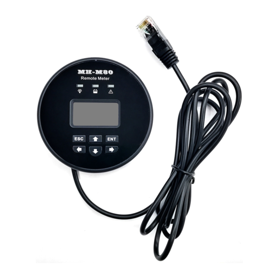
Expanded colloidal Instructions 1 pcs 3 pcs particles 1.5 Product features indicator light display window... - Page 10 Operation buttons Connecting cable Metal hanging plate limit detent Metal hanging plate mounting hole Metal hanging plate assembly Magnet buckle Limit slot...
-
Page 11: Installation Instructions
Application 1: when the MPPT controller is an iron shell or installed on an iron plate, mh-m80 can be directly adsorbed on the controller shell or iron plate through the magnet buckle on the back;... -
Page 12: Installation Steps Of Accessory Hanging Plate
2.2 Installation steps of accessory hanging plate Step 1: place the hanging plate assembly at the position to be installed, mark the hole position on the installation wall, drill 3 holes positions at the marked position, and fill the plastic expansion rubber sleeve (or make 3 M3 screw holes at the marked position). - Page 13 Step 2: fix the hanging plate assembly on the hole position made in step 1 with counter sunk 3mm self tapping screw or M3 screw. Step 3: align the limit slot hole on the back of the monitoring unit with the limit snap pin of the hanging plate, to make the monitoring unit adsorb on the hanging plate.
- Page 14 Step 4: connect the RJ45 plug of the connecting cable of the monitoring unit to the RJ45 communication port of the controller. When the display screen is normally on, it indicates that the installation is successful.
-
Page 15: Operating Instructions
3. OPERATING INSTRUCTIONS ☛ The default communication address of the monitoring unit is 1. In order to ensure normal communication between the controller and the monitoring unit, please give priority to ensuring that the controller address is consistent with the monitoring unit. ☛... -
Page 17: Main Menu Page
3.2 Main menu page As shown on the right of the figure above, the main menu page is divided into two function entries: parameter setting and trend chart. Use ↑ ↓ key to select the required function item, press ENT key to enter the selected function page, and press ESC key to return to the previous page. -
Page 18: Address Setting
3.3.1 Address setting The user can use this setting item to modify the device address of MPPT controller (only one MPPT controller can be accessed when using this function, and the same device address will be set if multiple MPPT controllers are connected!), change the value by ↑ ↓ key, move the cursor position by ←... -
Page 19: Charging Parameter Setting
3.3.2 Charging parameter setting The user can use this setting to modify the charging parameters of MPPT controller, change the value with ↑ ↓, move the cursor with ← →, press ENT to save the set parameters, and press ESC to return to the previous page. -
Page 20: Protection Parameter Setting
3.3.3 Protection parameter setting After setting the charging parameters, the user can set the protection parameters, change the value by ↑ ↓ key, move the cursor by ← →, press ENT key to save the setting parameters, and press ESC key to return to the previous page. -
Page 21: Reset Mppt Controller
synchronization of the controller (subject to the local time), change the value with ↑ ↓ key, move the cursor with ← →, press ENT key to save the setting, and press ESC key to return to the previous page. 3.3.5 Reset MPPT controller The user can initialize the controller data, press ENT to execute the reset action, and press ESC to return to the previous page. -
Page 22: Load Output Mode Setting
3.3.6 load output mode setting As shown in the figure below, when the cursor is in the load mode position, you can select different modes by pressing ↑ ↓, move the cursor by pressing ← →, and press ESC to return to the previous page. - Page 23 Select different control modes and different setting content pages will appear. Change the required value by ↑ ↓ key, move the cursor by ← →, press ENT key to save the setting, and press ESC key to return to the previous page. Light control mode: Off mode:...
-
Page 24: Trend Chart Function Page
Time control mode: Fixed time light control mode: 3.4 Trend chart function page As shown in the figure below, the data items of today's charging power, daily power generation and monthly power generation will appear on... -
Page 25: Today Charging Power Trend
the trend chart function page. You can select the required data items by pressing ↑ ↓, enter the selected data items by pressing ENT, and return to the previous page by pressing ESC. 3.4.1 Today charging power trend As shown in the figure below, press ENT to enter the graphical interface. -
Page 26: Daily Power Generation Trend
displayed at the top of the graph. ☛ When the monitoring instrument is disconnected from the controller, the data will be lost 3.4.2 Daily power generation trend As shown in the figure below, press ENT to enter the graphical interface, and the monitoring instrument will obtain the daily power generation data of the last 31 days from the controller for display. -
Page 27: Monthly Power Generation Trend
3.4.3 Monthly power generation trend As shown in the figure below, press ENT to enter the graphical interface, and the monitoring instrument will obtain the monthly power generation data of the last 12 months from the controller for display. The first on the right is the data of this month, the first on the left is the data before 11 months, and the top displays the monthly maximum power generation value of the last 12 months. -
Page 28: Status Indication
4. STATUS INDICATION Green: It represents the state of load output. When it is always on, it indicates that it is currently in on mode and on state. When it flashes, it indicates that it is currently in on mode but does not meet the conditions of on. -
Page 29: Warranty
5. WARRANTY Maintenance procedure Before requiring maintenance, please refer to the user's manual or contact the after-sales personnel by telephone to determine whether there is a problem with the product. If it is confirmed that it is necessary to return to the factory for repair, please express the defective products to our company, prepay the freight and provide the bill information related to the purchase as the warranty basis. -
Page 30: Appendix
6. APPENDIX RJ45 interface pin definition Function RS485-A RS485-B Dry Contact Dry Contact GND(isolation) GND(isolation) +5V(isolation) +5V(isolation)
Need help?
Do you have a question about the MH-M80 and is the answer not in the manual?
Questions and answers