Table of Contents
Advertisement
Quick Links
1.
OVERVIEW.......................................................................................................................................... 1
2.
INSTALLATION................................................................................................................................... 3
2.1. OPTICAL CONNECTIONS......................................................................................................... 3
2.1.1. Single Fiber Versions ...................................................................................................... 4
2.1.2. Standard Dual Fiber Version (-F2 version)...................................................................... 4
2.2. SIGNAL CONNECTIONS ........................................................................................................... 5
2.2.1. Multi-Pin Terminal Block Installation ............................................................................... 5
2.2.2. Serial Data Connections ................................................................................................. 7
2.2.3. LTC Connections ............................................................................................................ 8
2.2.4. GPIO Connections (7707DT-GPIO Versions Only)......................................................... 8
2.3. GENERAL PURPOSE INPUTS AND OUTPUTS ....................................................................... 8
2.4. CARE AND HANDLING OF OPTICAL FIBER........................................................................... 9
2.4.1. Safety .............................................................................................................................. 9
2.4.2. Assembly......................................................................................................................... 9
2.4.3. Labeling......................................................................................................................... 10
2.4.4. Handling and Connecting Fibers ................................................................................... 10
3.
SPECIFICATIONS............................................................................................................................. 11
3.1. RS-422/485 SERIAL DATA...................................................................................................... 11
3.2. RS-232 SERIAL DATA............................................................................................................. 11
3.3. LTC DATA ................................................................................................................................ 11
3.4. GENERAL PURPOSE INPUTS (7707DT-GPIO ONLY)........................................................... 11
3.5. GENERAL PURPOSE OUTPUTS (7707DT-GPIO ONLY)....................................................... 11
3.6. OPTICAL INPUT/OUTPUT....................................................................................................... 12
3.7. ELECTRICAL ........................................................................................................................... 12
3.8. PHYSICAL ................................................................................................................................ 12
4.
CARD-EDGE MONITORING AND CONTROL ................................................................................. 13
4.1. STATUS INDICATOR LEDS .................................................................................................... 13
4.2. CARD-EDGE DISPLAY AND CONTROLS .............................................................................. 14
4.2.1. Card-Edge Display Warning Indications........................................................................ 16
4.2.2. Displaying the Optical Power ........................................................................................ 16
4.2.3. Selecting the Signal Status Indication Mode ................................................................. 16
7707DT RS-232/422/485 Fiber Data Transceiver
TABLE OF CONTENTS
Revision 1.8
7700 MultiFrame Manual
Page - i
Advertisement
Table of Contents

Related Manuals for Everlz 7707DT

Summary of Contents for Everlz 7707DT
-
Page 1: Table Of Contents
2.2.1. Multi-Pin Terminal Block Installation ................5 2.2.2. Serial Data Connections ....................7 2.2.3. LTC Connections ......................8 2.2.4. GPIO Connections (7707DT-GPIO Versions Only)............8 2.3. GENERAL PURPOSE INPUTS AND OUTPUTS ............... 8 2.4. CARE AND HANDLING OF OPTICAL FIBER................9 2.4.1. - Page 2 6.4. LINK TRAPS........................23 ISTA ® APPENDIX - MPK ROUTER CONTROL INTERFACE TO 7707DT ..........24 7.1. OVERVIEW..........................24 7.2. INTERFACE METHODS......................26 7.2.1. MPK Interface to RS-422 ....................26 7.2.2. MPK Interface to RS-485 ....................29 7.3. TERMINATION AND FAILSAFE BIAS ..................31 Page - ii Revision 1.8...
- Page 3 Figure 1-1: 7707DT Block Diagram........................2 Figure 2-1: 7707DT Rear Panels ..........................3 Figure 2-2: Terminal Block Wiring .........................5 Figure 2-3: 7707DT Terminal Block Signal Connections ..................6 Figure 2-4: 7707DT-GPIO Terminal Block Signal Connections................7 Figure 2-5: General Purpose Inputs and Outputs ....................9 Figure 2-6: Reproduction of Laser Certification and Identification Label ............10...
- Page 4 Jul 2003 First Official release - added info on CARD ID jumper for single fiber versions Aug 2003 Updated 7707DT-GPIO pinout and expanded descriptions for this option; Feb 2005 Updated Vistalink related items; Removed Local Fault jumper Added Master/Slave RS422 configuration...
- Page 5 Never look directly into an optical fiber. Non-reversible damage to the eye can occur in a matter of milliseconds. Do not hook up the 7707DT DWDM cards directly with a short fiber optic cable. The 7707DT DWDM cards produce +7dBm of power, which will damage the receiver if connected directly.
- Page 6 7700 MultiFrame Manual 7707DT RS-232/422/485 Fiber Data Transceiver This page left intentionally blank Page - vi Revision 1.8...
-
Page 7: Overview
The standard configuration transmits and receives over a single fiber. The dual fiber configuration is compatible with CWDM systems and is designed to transmit and receive over separate fibers. The optical output of the 7707DT is available in 1310nm, 1550nm, or any one of up to sixteen CWDM wavelengths. -
Page 8: Figure 1-1: 7707Dt Block Diagram
7700 MultiFrame Manual 7707DT RS-232/422/485 Fiber Data Transceiver Transmit Side Receive Side Fiber Optical/Link Ordering Ordering Fiber Type Links Budget Description Product Info Power Product Info Sensitivity Multi-Mode < 3km 7707DT13-F2 -7dBm 7707DT13-F2 -28dBm 1310nm on Tx & Rx fibers... -
Page 9: Installation
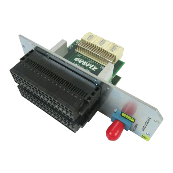
7700 MultiFrame Manual 7707DT RS-232/422/485 Fiber Data Transceiver INSTALLATION The 7707DT series modules come with a companion rear plate that has multi-pin removable terminal block connections, and an SC/PC (shown), ST/PC or FC/PC optical connector. For information on mounting the rear plate and inserting the module into the frame see section 3 of the 7700FR chapter. The following diagram shows four rear plate options. -
Page 10: Single Fiber Versions
7707DT. This connector should be connected to the matching connector of a matching single fiber 7707DT module at the destination end with a suitable fiber optic cable. All single fiber versions of the 7707DT are designed to work with single-mode fiber optic cable. -
Page 11: Signal Connections
Please refer to Figure 2-3 and Figure 2-4. GPIO: On the 7707DT-GPIO versions, these multi-pin terminal blocks have the connections for bi-directional General Purpose Inputs and Outputs (GPIO). The GPIO cables can be secured into the removable portion of the terminal strips using a small screwdriver. -
Page 12: Figure 2-3: 7707Dt Terminal Block Signal Connections
7700 MultiFrame Manual 7707DT RS-232/422/485 Fiber Data Transceiver Figure 2-3 and Figure 2-4 show the pinout diagram for the terminal blocks of both the 7707DT and the 7707DT-GPIO versions. Please note that input/output functions of RS-422/485 pins change with configuration. The following sections describe functionality of each pin designation:... -
Page 13: Serial Data Connections
RS-232 OUT (-) LTC (-) LTC Figure 2-4: 7707DT-GPIO Terminal Block Signal Connections 2.2.2. Serial Data Connections +RS485/+RS422 IN: Positive RS-422 input, or RS-485 input/output. When the associated channel is configured for use with RS-485, this pin becomes an RS-485 input/output. When the associated channel is configured for use with RS-422, this pin becomes an RS-422 input. -
Page 14: Ltc Connections
2.3. GENERAL PURPOSE INPUTS AND OUTPUTS The 7707DT-GPIO provides the user with 8 General Purpose Inputs (GPI’s) and 8 General Purpose Outputs (GPO’s). Figure 2-5 shows the input and output circuitry. Refer to sections 3.4 and 3.5 for electrical specifications. The GPI input stage uses opto-isolators for isolation. The GPO output stage uses dry contact relay closures. -
Page 15: Care And Handling Of Optical Fiber
7700 MultiFrame Manual 7707DT RS-232/422/485 Fiber Data Transceiver In te rn a l + 5 V C u rre n t L im itin g G P O 1 (1 0 m A ) G P I 1 C u rre n t... -
Page 16: Labeling
There is no date of manufacture on this label as it can be traced by the bar code label placed on the Printed circuit board of each Evertz plug-in module • The Model number is one of: 7707DT-13, 7707DT13-GPIO, 7707DT13M-W, 7707DT13M-W-GPIO, 7707DT15-W, 7707DT15-W-GPIO, 7707DT13-F2, 7707DT13-F2-GPIO •... -
Page 17: Specifications
7700 MultiFrame Manual 7707DT RS-232/422/485 Fiber Data Transceiver SPECIFICATIONS 3.1. RS-422/485 SERIAL DATA Number of Signals: 4 Inputs/Outputs Connector: Multi-pin Removable Terminal Block Signal Type: RS-485 or RS-422 (selectable) Input Termination: 110Ω or Open (selectable) Input Failsafe Bias: 200mV (3.3mA into 60Ω) or None (selectable) -
Page 18: Optical Input/Output
7700 MultiFrame Manual 7707DT RS-232/422/485 Fiber Data Transceiver 3.6. OPTICAL INPUT/OUTPUT Connector: Single Fiber version: 1 Bi-directional optical connector: SC/PC, ST/PC or FC/PC female housing Dual Fiber (F2) version: 2 optical connector: SC/PC, ST/PC or FC/PC female housing Maximum Input Power:... -
Page 19: Card-Edge Monitoring And Control
7707DT RS-232/422/485 Fiber Data Transceiver CARD-EDGE MONITORING AND CONTROL The 7707DT has eight LED status indicators and a 4-digit dot-matrix display on the front card-edge to show operational status of the card at a glance. The card-edge pushbutton and toggle switch are used to select various indications to the dot-matrix display and LED’s. -
Page 20: Card-Edge Display And Controls
LED 12 RS-232 Channel 8 LED 13 The 7707DT-GPIO provides additional status indicator modes, where LED1 through LED8 describe the states of the respective GPI or GPO channels. CONTROL: This yellow LED is no longer considered by recent code versions, and if installed, should be disregarded by the user. -
Page 21: Figure 4-2: Card-Edge Menu Quick Reference
7700 MultiFrame Manual 7707DT RS-232/422/485 Fiber Data Transceiver Menu Level 1 Menu Level 2 Menu Level 3 Menu Level 4 Pushbutton Pushbutton Pushbutton Pushbutton Menu Selections: Configuration Values: LASR…ERR (Laser Error) Overrides LINK…LOS (Link Loss) Overrides -40 to +04 (dBm) -
Page 22: Card-Edge Display Warning Indications
Optical link established, no video input or laser (if equipped) problems. 4.2.2. Displaying the Optical Power The 7707DT can measure and display optical power over a range of –40 to 0dBm in 1dBm increments. Please heed the maximum optical input power specification for the specific product option you possess. - Page 23 RS-232 Channel 8 LED 13 The 7707DT-GPIO provides additional status indicator modes, where each LED describes the state of the respective GPI or GPO channel. To change the card-edge LED indicator mode, select the STAT menu item in menu level 1. Toggle to the desired status indication selection shown in the list below.
-
Page 24: Selecting The Serial Data Type
® To select the serial data type, select the CTRL menu item in menu level 1. The 7707DT allows the data type to be set independently for each channel. Use the toggle switch to choose the channel to which the selection will be applied. -
Page 25: Selecting The Serial Data Termination
® To turn the termination on or off, select the CTRL menu item in menu level 1. The 7707DT allows terminations to set independently for each channel. Use the toggle switch to choose the channel to which the selection will be applied. Press the pushbutton to apply the displayed selection. -
Page 26: Selecting The Serial Data Failsafe Bias
® To turn the failsafe bias on or off, select the CTRL menu item in menu level 1. The 7707DT allows a failsafe bias threshold to be set independently for each channel. Use the toggle switch to choose the channel to which the selection will be applied. -
Page 27: Jumper Controls
CARD ID: To maintain a link between two 7707DT cards, set this jumper to position A on one, and to position B on the other. Position B may be selected on either of the cards, as long as position A is selected for the companion card. -
Page 28: Vistalink ® Remote Monitoring/Control
Evertz VistaLINK enabled fiber optic products. ® 2. Managed devices (such as 7707DT cards), each with a unique address (OID), communicate with the NMS through an SNMP Agent. Evertz VistaLINK enabled 7700 series modules reside in the 3RU ®... -
Page 29: Vista Link ® Controlled Parameters
7700 MultiFrame Manual 7707DT RS-232/422/485 Fiber Data Transceiver 6.3. LINK CONTROLLED PARAMETERS ISTA ® The following parameters can be remotely controlled via the VistaLINK interface. ® Parameter Description Data Type Data Type Control. See section 4.2.4 Data Rate Data Rate Control. See section 4.2.5 Cable Termination Input Termination Control. -
Page 30: Appendix - Mpk Router Control Interface To 7707Dt
The MPK control interface uses a proprietary method of signaling, for which special considerations are required when connecting to other interface types. This application note describes methods for using the 7707DT Fiber Data Transceiver to transport MPK control signals. The 7707DT series Fiber Data Transceivers communicate bi-directional RS-422 and RS-485 data signals over a single fiber optic link. -
Page 31: Figure 7-1: Rs-422 Interface Example
7700 MultiFrame Manual 7707DT RS-232/422/485 Fiber Data Transceiver RS-422 Device RS-422 Device Figure 7-1: RS-422 Interface Example RS-485 Device RS-485 Device RS-485 Device Each device ouputs data in-turn to all other devices. RS-485 Device Figure 7-2: RS-485 Interface Example Control Panel... -
Page 32: Interface Methods
From the above overview, it is apparent that special considerations are required when connecting MPK interface signals to the RS-422 or RS-485 interface of the 7707DT. The issue at hand is the high- impedance state that each Control Panel assumes between data transmissions. If several control panel outputs are to be connected together, then this high-impedance state is required to avoid contention of the shared output connection. -
Page 33: Figure 7-5: Mpk Interface To Rs-422 - Incorrect Method
7700 MultiFrame Manual 7707DT RS-232/422/485 Fiber Data Transceiver Control Panel Control Panel Control Panel Set to RS-422 Control Panel output will contend with 7707DT output. W ill not work. Incorrect Method 7707DT Set to RS-422 Jupiter System Controller 7707DT Figure 7-5: MPK Interface to RS-422 - Incorrect Method Page - 27 Revision 1.8... -
Page 34: Figure 7-6: Mpk Interface To Rs-422
7700 MultiFrame Manual 7707DT RS-232/422/485 Fiber Data Transceiver 7707DT Channel 1 is configured to RS-422 for this exam ple. Control Panel Control Panel 7707DT 7707DT - T X +T X +RS485 +RS485 -RS422 OUT -RS422 OUT +RS422 IN +RS422 IN... -
Page 35: Mpk Interface To Rs-485
7707DT RS-232/422/485 Fiber Data Transceiver 7.2.2. MPK Interface to RS-485 A second interface method exists, which allows Control Panels to be located on both ends of the 7707DT fiber link. This method is only advantageous should available ports be limited on the System Controller. -
Page 36: Figure 7-8: Mpk Interface To Rs-485
7700 MultiFrame Manual 7707DT RS-232/422/485 Fiber Data Transceiver 7707DT Channel 1 is configured to RS-422 for this exam ple. Control Panel Control Panel 7707DT Channel 2 is configured to RS-485 @ 1200baud for this exam ple. 7707DT 7707DT - T X... -
Page 37: Termination And Failsafe Bias
7707DT be located at the far end of the longest cable segment when possible. The 7707DT also provides a selectable bias on the balance data inputs. This is referred to as a failsafe bias, as it places the balanced input connections in a known logic state while no device is transmitting to them. - Page 38 7700 MultiFrame Manual 7707DT RS-232/422/485 Fiber Data Transceiver This page left intentionally blank Page - 32 Revision 1.8...
Need help?
Do you have a question about the 7707DT and is the answer not in the manual?
Questions and answers