Table of Contents
Advertisement
Quick Links
Advertisement
Table of Contents

Summary of Contents for Proline PROMAX MIG-250DP
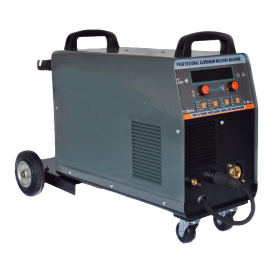
- Page 1 Owners Manual MIG-250DP...
- Page 2 This product is backed by a 12-month trade warranty. Proline Welding Supplies would like to thank you for your business, we look forward to as- sisting with any technical support or welding supplies required to keep your welder operating.
-
Page 3: Safety Instructions And Warnings
SAFETY INSTRUCTIONS AND WARNINGS Symbol Usage This manual contains important information that you need to know and understand in order to assure YOUR SAFETY and PROPER OPERATION of EQUIPMENT. The following symbols help you recognize this information. Please read the manual and pay attention to these sections. - Page 4 Do not touch live electrical parts. Wear dry, hole-free insulating gloves and body protection. Insulate yourself from work and ground using dry insulating mats or covers big enough to prevent any physical contact with the work or ground. Do not use AC output in damp areas, if movement is confined, or if there is a danger of falling.
- Page 5 necessary, while wearing an air-supplied respirator. The coatings and any metals containing these elements can give off toxic fumes if welded. Shut off shielding gas supply when not in use. ARC RAYS can burn eyes and skin. Arc rays from the welding process produce intense visible and invisible (ultraviolet and infrared) rays that can burn eyes and skin.
- Page 6 HOT PARTS can cause severe burns. Do not touch hot metal barehanded. Allow cooling period before working on gun or torch. MAGNETIC FIELDS can affect pacemakers. Pacemaker wearers keep away. Wearers should consult their doctor before going near arc welding, gouging, or spot welding operations. NOISE can damage hearing.
- Page 7 INTRODUCTION This highly developed digital controlled welder unit adopt advanced chip programmed inverter IGBT technology , It serves for versatile welding process which integrate MIG/MAG gas welding , flux cored wire welding , MMA and TIG lift welding .The welder was developed for semi industrial welding purpose , suitable to weld a wide range of materials like aluminum , aluminum alloy , low carbon steel , low alloy steel, stainless steel , etc .
- Page 8 12. Intelligent cooling fan, that switches to sleep mode automatically during no-load condition , and prolong service life of welding machine . energy saving . 13. Intelligent saving of welding specification . 14. Can be connect to robot automatic welding equipment . 15.
- Page 9 1. LED display. 2. Set of knobs - buttons for setting all available parameters: a. left knob: - rotation - welding current adjustment, - pressing and holding - wire feed test, b. right knob: - rotation - voltage correction expressed in [V] or [%], - short press - change units [V] or [%].
- Page 10 selection of materials items materials wire diameter description Welding of carbon steels by the MAG method FeC/Co2 Fe CO2 0.8/1.0mm CO2 shield. Welding of carbon steels by the MAG method FeC/ArCo2 Fe Ar82 0.8/1.0mm Ar + CO2 gas mixture cover. Welding of stainless steels E308 Ar98 0.8/1.0mm...
- Page 11 ADVANCED MENU AND SETTINGS Advanced menu - method selection. Pressing both knobs simultaneously (but in order first right then left) causes entry advanced menu devices. Then the display will show the symbol of the currently set welding method. By turning the right rotary knob you can select the desired welding method e.g. Pulse TIG which is not available in quick selection menu.
- Page 12 Pulsation frequency when welding with double pulse MIG 2-Pulse. Double pulse balance for double pulse welding Peak current amplitude when welding with double pulse Correction of the peak voltage (arc length) when welding with double pulse. Correction of the voltage (arc length) of the base current when welding with double pulse.
- Page 13 A special two-act with Hot Start and final current (filling) crater). Pressing the MIG torch button initiates the flow of gas and hot start current to the set Hot I values, which lasts according to the set Hot time. After the time Hot t has elapsed, the current drops to the "normal" welding current. Duration of the current decreaseis the same as the Slop position.
-
Page 14: Storing And Recalling Settings
Storing and recalling settings. The device has 36 memory channels on which the user can save and recall any settings. 1. To save the settings, press the two knobs simultaneously and enter the menu Advanced. 2. Turn the left rotary knob to reach the Save position. 3. - Page 15 Connection Before connecting this device to the mains, check the voltages, number of phases and frequency. Power supply voltage parameters are given in the chapter with technical data of this manual and on the plate rated device. Check the connections of the device's ground wires to the mains. Make sure the mains can provide coverage of the input power requirement for this the device under normal operating conditions.
-
Page 16: Shielding Gas Connection
5. To enable wire insertion in the feeder, release the pressure of the feed rollers. 6. Insert the end of the wire into the guide at the back of the feeder and route it over with drive rollers and insert into the guide pipe into the welding gun. 7. -
Page 17: Recommended Wire Sizes
Selecting Wire Types For thin metals, use a smaller diameter wire. For thicker metal use a larger wire and a larger machine. See machine recommendations for welding capacity. Welding Wire Thickness Chart RECOMMENDED WIRE SIZES GASLESS FLUX-CORED MATERIAL MIG SOLID WIRE WIRE THICKNESS 024”... -
Page 18: Mma Welding
Holding and Positioning Welding Gun WELDING WIRE IS ENERGIZED WHEN GUN TRIGGER IS PRESSED, BEFORE LOEERING HELMET AND PRESSING TRIGGER,BE SURE WIRE IS NO MORE THAN 1/2 IN (13 MM)PAST END OF NOZZLE,AND TIP OF WIRE IS POSITIONED CORRECTLY ON SEAM. 1. -
Page 19: Maintenance
TIG LIFT welding The device described in this manual can be used for TIG LIFT welding. To do this, purchase a handle designed for this method - it is equipped with a mechanical handle protective gas valve placed in the handle. To TIG LIFT welding: Insert the welding cable plugs into their respective sockets and lock them (earth clamp to (+), TIG torch to (-)). - Page 20 Imported & Distributed by Phone: 0800 699 353 sales@prolinewelding.com Email: www.prolineindustrial.co.nz Website:...
Need help?
Do you have a question about the PROMAX MIG-250DP and is the answer not in the manual?
Questions and answers