
Related Manuals for ATO STC858A

Summary of Contents for ATO STC858A
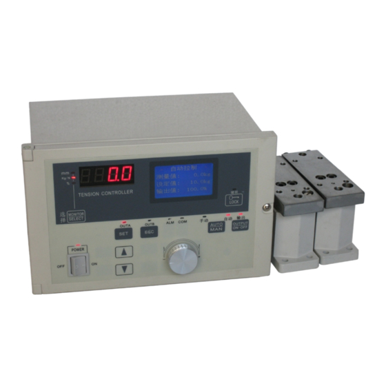
- Page 1 MODEL - STC858A AUTOMATIC TENSION CONTROLLER TENSION CONTROLLER Ver 3.0 INSTRUCTION MANUAL English version...
- Page 2 MODEL - STC858A ® LTC858A Cautions on Safety (Make sure to read this page before using the unit.) 安全注意事项 To assure safety When the unit is handled incorrectly, a Danger: dangerous situation may occur and the (请务 必在使 用 前阅读) >Make sure the user thoroughly read this instruction manual...
-
Page 3: Table Of Contents
MODEL - STC858A CONTENTS 1. Outline ..........1 Outline 1.2 Functions and features ......... 1 ....2 Panel configuration& Functions of DIP switches 2. Installation and Wiring 2.1 Dimensions ........... 4 2.2 Installation ..........4 2.3 Wiring ..........5 3. -
Page 4: Outline
Chapter 1 Product outline Outline STC858A tension controller is a full digital tension controller with high precision and multi-function which to match up tension detector to form a closed-loop tension controller system an then receives the signal from LS series tension... -
Page 5: Panel Configuration& Functions Of Dip Switches
MODEL - STC858A 1.3 Panel configuration 1. LCD display 22. Monitor display 2. Lockin LED 自动运行 自动运行 Kg/N 设定值 21. LED indicator 10.0Kg 3. Lockin key 设定值 10.0Kg 实际值 10.0Kg 实际值 10.0Kg 20.Screen selection keys 6. Manual indicator LED 输出值... - Page 6 MODEL - STC858A 7. OUTA : A shaft output indicator It's red indicator. when the A shaft outputting, the indicator will light. 8. OUTB : B shaft output indicator It's red indicator. When the B shaft outputting, the indicator will light.
-
Page 7: Installation And Wiring
MODEL - STC858A Chapter 2 installation and wiring Dimensions Unit:mm 自动运行 kg/N 自动运行 Kg/N 设定值 10.0Kg 设定值 10.0Kg 实际值 10.0Kg 实际值 10.0Kg KTC838 输出值 50.0% 输出值 Tension Controller 50.0% 键 锁 LOCK MONITOR TENSION CONTROLLER www.sunrisescn.com SELECT MODEL: STC858 POWER: 85~264VAC 50/60Hz INPUT:... -
Page 8: 2.3 Wiring
MODEL - STC858A 2.3 Wiring 2.3.1 Wiring method and cautions ➊ Use the crimp-style terminals. Dimensions shown in the right figure. ➋ Apply a torque of 0.5 to 0.8 Nm to each terminal, and carefully tighten each terminal so that abnormal operation cannot be caused. - Page 9 MODEL - STC858A DANGER ➲ Before installing the controller or performing the wiring work, be sure to externally cut off the power of all the phases. If the power of all the phases is not cut off, you may receive an electric shock, or the product may be seriously damaged.
-
Page 10: Screen System
MODEL - STC858A Chapter 1 Screen system Power-on Overall of screen system Priority order for screen selection at power-on. Tension controller (1) Memory cassette insertion screen STC858 (2) Parameter initialization screen (3) Adjustment mode screen www.ato.com Auto control Manual control AUTO Measuring value: 24.9kg... -
Page 11: Screen Introduction
MODEL - STC858A 3.2 Main Screen Introduction (1) Automatic control - constant tension mode screen Tension testing vale Automatic control : 24.9kg Testing value Using up key /down key or Set the knob to change the tension setting numerical values 25.0kg... - Page 12 MODEL - STC858A Parameter Description The following table have been classified based on function parameters. Parameter Name Description Parameter NO. Adjusting range Factory default Function selection parameters: the basic parameters of the following parameters should be set according to the actual situation of the first.
-
Page 13: Tension Detector Installation & Wiring
Tension detector installation and wiring STC858A accept a variety of tension detector input signals, to make the appropriate jumper settings for different detectors: Micro displacement special tension detector, the input signal range is 300mV, 5V power supply (such as the LS series, and mitsubishi tension sensor compatible) Sw1 switch settings are as follows:... -
Page 14: Tension Measuringparameter Settings
This controller can choose one or two tension detectors to work which based on tension detector installation conditions Settings. [24] Display unit STC858A can choose two units showing tension measuring value: "kg (kg)" and "N (Newton)" [25] Signal range The controller can choose two signals, ± 30mV and ± 300mV which depending on the installation of the detector selecting corresponding signal range. -
Page 15: Tension Demarcate
STC858A tension controller are adopted two linear calibration which calibration process is very simple. (1) Note [1] Before calibration, ensure that tension detector is wiring correctly, confirm the tension detector works properly, the tension signal is within the selected range. - Page 16 MODEL - STC858A (3) Full-scale calibration Tension detector Hang known weight load W (kg) Note: the weight of the load should not be less than ½ span of the tension detector. Tension detector Thread a string through the roller centers (1) Hang known wight W(kg) from the detector roller, refer to above drawing.
-
Page 17: Adjustment & Initial Setting
MODEL - STC858A Adjustment operation When tension was measured correctly, then enter to the automatic and manual operation mode of controller for adjustment. firstly operate it with manual control mode, when manual operation works normally, coil achieves proper and stable tension, then switch it to automatic control mode. -
Page 18: Pi Parameter Setting
4.2.3 When STC858A in automatic control mode, proportion, integral, static area parameter values influence the stability and control precision of system, such as tension control is unstable which need to adjust and set the appropriate proportion, integral and static area parameter values. -
Page 19: Operation At Starting Or Stopping Machine
MODEL - STC858A 4.2.4 System start and stop Start and stop control S1connecting Start NPN pulse signal S1 shutdown Stop Detector roller pulse input wiring diagram S1:Start-stop switch Start, stop of STC858 Tension Controller is controlled by the terminal MC1, MCC, MC1, MCC terminals connect to a switch which switch (S1) is the system start -stop switch, connecting or shutdown of S1 switch will start or stop the tension system operation. -
Page 20: Dual Axis Switching
Switch close up: B shaft running The axis swithcing of STC858A tension controller is controlled by terminals MC2, MCC when MC2, MCC terminals switch is on/off which means the axis switching switch of the system will be on/off. When the axis switching switch is off, then A axis runs;... - Page 21 MODEL - STC858A Axis switching switch When the axis switching switch is off, A axis runs; When the axis switching switch is shorted, B axis runs; A axis runs A axis runs A axis runs B axis runs Axis switching time...
-
Page 22: Speed Up/Slow Down Controlling
MODEL - STC858A 4.2.6 Acceleration / deceleration control Connect a button to MC3, MCC, when the system needs to speed (the acceleration/deceleration), press the button, then the output value is output value of cut moment multiplied by accelerated coefficient [16], make the system acceleration and deceleration. -
Page 23: Alarm Function
Esc/exit Zero tension alarm value 4.2.8 Feedback method This parameter controls feedback of STC858A : 40.Feedback method N ; ormal mode: When the tension measurement value is larger than the tension set value, Normal mode then the output decreases which is negative feedback method. -
Page 24: Taper Tension Controlling
MODEL - STC858A Tapper tension control 4.3.1 Taper Control Overview In rewinding system, along with the increase of reel diameter, making the control of the coil material tension reduced gradually called as taper tension control, taper control can make inner lining of rewinding membrane lining very tightly, and make the outer membrane very loose, thus make coil material film between layers without slippage , to prevent materials winding roll from too tightly and coil winding skewed. -
Page 25: Other Functions
MODEL - STC858A Chapter 5 Other Functions Language selection STC858A can choose Chinese or English interface 32.Chinese/English (1) Enter into Simplified / Traditional / English [32] parameter screen Simplified Chinese Using ▲/▼ keys or numerical set knob t o select language Traditional Chinese (3)... -
Page 26: Inspection And Maintenance
MODEL - STC858A Chapter 6 Inspection and manitenace Solution Problem Possible malfunction > Power problem Make sure the supply voltage of the controller is 180-264 V/AC When the power is turned 1.If this value is not correct, perform the correct wiring。... -
Page 27: Appendixes
MODEL - STC858A Chapter 7 Appendix Parameter screen 03.Tapper coefficients 04.Tension alarm value 01.Display filter coefficients 02.Output filter coefficients 05.Proportional band AL1= 0.0kg PROP= 100.0kg FIL= 3.00 t1= 0.00 FIL= 0.0second Set/confirm Esc/exit Set/confirm Esc/exit Set/confirm Esc/exit Set/confirm Esc/exit Set/confirm Esc/exit 06. -
Page 28: Tension Detector Operation Principle
MODEL - STC858A 7.2 Tension detector work principle LS – TD tension detector is a measuring instruments which using high precision differential transformer to test the leaf-spring bending degree(approx.±200μm) when it roles by load. Related load is 50--1000N。 Load Block support point Note:This tension detector needs to be matched with tension controller or tension meter to use. -
Page 29: Dimension Specification
MODEL - STC858A 4-M6 7.3 Dimensions 2-M10 Aviation plug Length of line 3m Length of line 15cm Aviation plug 4-ø6.5 4-M6 (4 holes for left & right side) mounting hole 7.4 Assembling Screw must not be too long, in order to avoid topping to micro partial area. -
Page 30: Technical Specifications
MODEL - STC858A 7.6 Specifications Tension detector special for slight movement ( input signal 200mV, Power supply 5VDC0 Tension signal ±0.2%FS±1 Measuring precision Sampling period 100ms PI(PI calculation Control calculation Two 24VDC/4A output, drives magnetic clutch / brake directly Main output...
Need help?
Do you have a question about the STC858A and is the answer not in the manual?
Questions and answers