Table of Contents
Advertisement
Quick Links
Advertisement
Table of Contents

Summary of Contents for WORKMASTER TO-A02
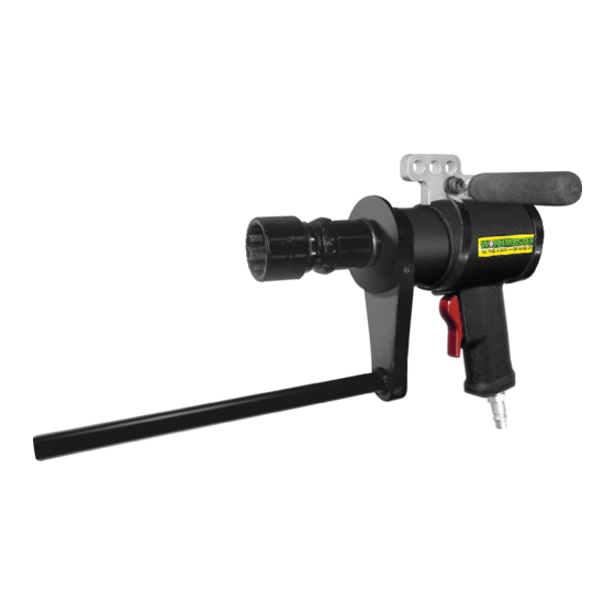
- Page 1 TO-A02 Trailer Trap Opener OWNER / OPERATOR MANUAL...
- Page 2 The user of this product is responsible to install, maintain and operate the product and parts or components manufactured or supplied by WORKMASTER in such a manner as to comply with all federal, state and local rules, ordinances, regulations and laws, including the Williams-Steiger Occupational Safety Act, and the American National Standards Institute Safety Code.
- Page 3 SYMBOLS The following symbols are found throughout this Operator's Guide to alert the reader to the relative danger that may result from non-observance. This indicates a situation in which a hazard is imminent and will result in a high probability of serious injury or death.
-
Page 4: Table Of Contents
SECTION PAGE Introduction Safety III. Required Materials Pre-Start Checklist Assembly Operation VII. Storing Your TO-A02 Trap Opener Figure 1 Trailer Type Drive Fittings Figure 2 TO-A02 Opener Kit Figure 3 Forward / Reverse Trigger Figure 4 Dimension Template Appendix A... -
Page 5: Introduction
This Owner/Operator Manual details the specifications, operation, maintenance and safe use of the TO-A02 Pneumatic Trailer Trap Opener. Experience has shown that the TO-A02 Opener will rapidly and safely open any trap. However, the same experience... -
Page 6: Safety
It is the responsibility of the owner and operator to install, maintain, and operate the parts or components manufactured and supplied by WORKMASTER, in such a manner as to comply with the Williams-Steiger Occupational Safety Act and with all state and local laws, ordinances, regulations, and the American National Standards Institute Safety Code (ANSI). - Page 7 Trailer Trap being opened (Strap vs Rack & Pinion). Damage will occur if excess PSI is used. CAUTION Use only Drive Fitting Accessories recommended by WORKMASTER. Do not carry the Tool by the hose. Inspect, maintain, operate, and install the Opener in accordance with all applicable standards and regulations (local, state, country, federal, etc) Keep clear of whipping air hoses.
-
Page 8: Required Materials
III. REQUIRED MATERIALS The following items are not supplied with your WORKMASTER Trap Opener but are necessary for its proper installation and operation. CLEAN and DRY Compressed Air High Quality Air Hose from the Compressor to the WORKMASTER supplied FRL: 1/2" (for ≤25ʹ from supply) / 3/4" (for >25ʹ from supply); fitted with 1/2"... -
Page 9: Pre-Start Checklist
On the WORKMASTER FRL, adjust the air pressure by using the Air Regulator Knob to set the desired pressure / torque. With the TO-A02 not on the Capstan, press the trigger and adjust the Regulator pressure at the same time. - Page 10 Figure 1: Trailer Type Drive Fittings The torque settings have to be considered only as a guideline. Because of variations in pressure and/or air flow, as well as other application issues, deviations may be necessary. Due to the CFM required, when the Opener is running at free speed, it may not be CAUTION possible to set the Regulator to the desired pressure...
- Page 11 For extreme cold weather, use approved cold weather pneumatic tool lubrication to prevent freeze ups. IMPORTANT Do not fold or bend the supply hose excessively, and check all hoses for damage before use. A damaged hose must not be used, as there is a risk of a hose burst.
-
Page 12: Assembly
V. ASSEMBLY The TO-A02 comes assembled and ready to use. Follow the steps below to connect Airline and verify pressure setting on the supplied FRL Unit. as shown in Verify you are familiar with each of the supplied Items Figure 2:... -
Page 13: Operation
Trailer Trap being opened. Damage will occur if excess PSI is used. CAUTION 1. Place your TO-A02 Drive Fitting completely into/over the Trailer Trap to be opened or closed. 2. Ensure the torque reaction area of movement is taken up by the Reaction Arm. - Page 14 Seek medical advice before resuming. 4. After pressing the trigger on the pistol grip to open the Trap, the TO-A02 will rotate until it becomes torqued, the tool will then stall out. Keep your body stance balanced and firm. Do not overreach when operating this Tool.
- Page 15 6. When closing a Trap, the Tool will continue to rotate until the Trap is closed. 7. Continue the process for opening or closing each Trap. Add, if necessary, the appropriate Drive Fitting Adaptor as shown in Figure 1: Trailer Type for the next Trap Drive Fittings, P6 .
-
Page 16: Storing Your To-A02 Trap Opener
4. If the TO-A02 Opener is not to be used for an extended period of time, spray pneumatic lubricating oil into the TO-A02's Inlet Fitting. Reconnect the air hose and supply hose to the FRL Unit's air inlet fitting. -
Page 17: Appendix A Air Preparation Kit
APPENDIX A. AIR PREPARATION KIT 32-70801 Filter, Regulator, Lubricator and Fitted Hose Assembly ITEM PART # DESCRIPTION WM-FRL-001 Precision Regulator WM-FRL-001-K Knob for Precision Regulator WM-FRL-002 Lubricator Unit WM-FRL-002-B Bowl Assembly for Lubricator Unit WM-FRL-002-SG Sight Glass for Lubricator Unit WM-FRL-003 Filter with Auto Drain WM-FRL-003-B... -
Page 18: Appendix B Parts List
APPENDIX B. PARTS LIST DRIVE ASSEMBLY ITEM QTY. PART # DESCRIPTION WM-AM19-ASSY HANDLE AND MOTOR ASSEMBLY WM-AM19-41 AIR MOTOR BALL RETAINER WM-CM-BB STEEL BALL WM-05-ST-G SPUR GEAR WM-05-ST1 STAGE GEAR CAGE WM-ST-GW SPUR GEAR WM-05-ST2 STAGE GEAR CAGE WM-05-HSA HIGH SPEED ANNULUS WM-05-DOWEL LONG HARDENED DOWEL WM-05-TW... - Page 19 APPENDIX B. PARTS LIST HANDLE & MOTOR ASSEMBLY \ ITEM PART # DESCRIPTION WM-AM19-01 HANDLE HOUSING WM-AM19-03 GASKET WM-AM19-11-1 MOTOR ASSEMBLY WM-AM19-21 BACKHEAD SPACER WM-AM19-23 BACKHEAD WM-AM19-25 TRIGGER WM-AM19-27 SNAP RING WM-AM19-29 POPPET VALVE ASSEMBLY WM-AM19-33 INLET BUSHING O-RING WM-AM19-35 INLET BUSHING WM-AM19-37 INLET BUSHING CAP SCREW...
- Page 20 APPENDIX B. PARTS LIST AIR MOTOR ASSEMBLY ITEM PART # DESCRIPTION WM-AM19-05 FRONT BEARING WM-AM19-07 FRONT END PLATE WM-AM19-09 DOWEL WM-AM19-11 MOTOR HOUSING WM-AM19-13 VANES WM-AM19-15 ROTOR WM-AM19-17 BACK END PLATE WM-AM19-19 BACK BEARING PH: 866.476.9217...
- Page 21 APPENDIX B. PARTS LIST POPPET VALVE ASSEMBLY ITEM PART # DESCRIPTION WM-AM19-29-1 POPPET VALVE BODY WM-AM19-29-2 POPPET VALVE STEM WM-AM19-29-3 POPPET VALVE SMALL O-RING WM-AM19-29-4 POPPET VALVE WM-AM19-31 POPPET VALVE SPRING WM-AM19-33 POPPET VALVE LARGE O-RING PH: 866.476.9217...
-
Page 22: Appendix C Technical Specifications & Dimensions
APPENDIX C. TECHNICAL SPECIFICATIONS & DIMENSIONS Model Number TO-A02 Tool Max Pressure 80 psi Height 7.89" RPM @ 80 psi Length 6.90" RPM @ 20 psi Diameter 2.56" RPM @ 40 psi Square Drive 3/4" Max. Torque (ft lbf) Weight w/o Reaction Arm 9 lbs Min. -
Page 23: Appendix D Calibration Chart
APPENDIX D. CALIBRATION CHART Model: TO-A02 81 to 448 Torque Range ft-lbf: Accuracy: ± 5% Set Torque FT-LBF FT-LBF FT-LBF PH: 866.476.9217... - Page 24 NOTES PH: 866.476.9217...
- Page 25 NOTES PH: 866.476.9217...
- Page 26 NOTES PH: 866.476.9217...
- Page 27 NOTES PH: 866.476.9217...
- Page 28 Ask about other Exciting Unloading Products Such as . . . Distributed By: 866.476.9217 866.476.9219 PN: 10-00081...
Need help?
Do you have a question about the TO-A02 and is the answer not in the manual?
Questions and answers