
Summary of Contents for Fastech Ezi-SERVOII EtherCAT TO
- Page 1 Closed Loop Stepping System EtherCAT Network User Manual • Ezi-SERVOII EtherCAT TO FASTECH Co., Ltd.
-
Page 2: Table Of Contents
........CiA402 Drive Profile Rev.37 FASTECH Co., Ltd. - Page 3 ........Rev.37 FASTECH Co., Ltd.
- Page 4 ..... 6.5.32 Object 60BCh: Touch probe 2 positive value ..... Rev.37 FASTECH Co., Ltd.
- Page 5 ......105 6.6.25 Object 2031h: Encoder count error ......106 Changelog Rev.37 FASTECH Co., Ltd.
-
Page 6: Introduction
Before Operation • Thank you for your purchasing Ezi-SERVOII EtherCAT TO. • 32 Bit high-performance of ARM Processor on-board Ezi-SERVOII EtherCAT TO is motion con- troller supports Field-network EtherCAT. • This manual describes handling, safety instruction, diagnosis and troubleshooting of Ezi-SERVOII EtherCAT TO. -
Page 7: Safety Precautions
• Contents of this manual are subject to change without prior notice for functional improvement, change of specifications or user’s better understanding. • When the manual is damaged or lost, please contact with Fastech’s agents or our company to get a manual again. - Page 8 Before connecting cables, please check if input power is OFF. Otherwise, a fire or other kinds of accidents may occur. The case of Ezi-SERVOII EtherCAT TO is insulated from the ground of the internal circuit by the condenser so please ground the product. Otherwise, an electric shock or a fire may occur.
- Page 9 Do not change cabling while power is being supplied. Otherwise, the user may get injured or the product may get damaged. Do not reconstruct the product. Otherwise, an electric shock may occur or the reconstructed product can not get After Sales Service. Rev.37 FASTECH Co., Ltd.
-
Page 10: Product Specification
Chapter 1 Product Specification Rev.37 FASTECH Co., Ltd. -
Page 11: Model Naming
BK : Brake Reduction Gear Ratio Blank – Without Gear PN03 – 1:3 PN05 – 1:5 PN08 – 1:8 PN10 – 1:10 PN15 – 1:15 PN25 – 1:25 PN40 – 1:40 PN50 – 1:50 Figure 1.1: Model Naming Rev.37 FASTECH Co., Ltd. -
Page 12: Product Dimension
1. Product Specification 1.2 Product Dimension Figure 1.2: Dimensions Rev.37 FASTECH Co., Ltd. -
Page 13: Ethercat Specifications
CiA402 drive profile (IEC61800-7) Cyclic Synchronous Position Mode Supported Operation Mode Profile Position Mode Homing Mode Free Run, SM Event, DC SYNC Event Synchronization (minimum cycle time: 250us) Processing Data Configurable PDO Mapping Table 1.1: Communication Specification Rev.37 FASTECH Co., Ltd. -
Page 14: Drive Specification
Power status, In-Position status, Servo On status, Alarm status 3 dedicated input (LIMIT+, LIMIT-, ORIGIN) Input Signals 6 user inputs (Photocoupler Input) TQOFF Input I/O Signal Brake Output Signals 5 user outputs (Photocoupler Output) TQMON Output Table 1.2: Drive Specification Rev.37 FASTECH Co., Ltd. -
Page 15: Installation
Chapter 2 Installation Rev.37 FASTECH Co., Ltd. -
Page 16: Precautions Of Installation
3. Do not install this product under direct rays or near magnetic or radioactive objects. 4. If more than 2 drives are installed in a line, keep the interval of 20mm or more vertically and 50mm or more horizontally at least. over 50mm over 20mm Rev.37 FASTECH Co., Ltd. -
Page 17: System Configuration
2. Installation 2.2 System Configuration Figure 2.1: System Configuration Diagram Rev.37 FASTECH Co., Ltd. -
Page 18: External Wiring Diagram
2. Installation 2.3 External Wiring Diagram Figure 2.2: External Wiring Diagram Rev.37 FASTECH Co., Ltd. -
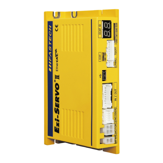
Page 19: Appearance And Part Name
• If Rotary switch set as not 0 but other value, 7-Segment indicates relevant set value (EtherCAT configured Alias). • If 7-Segment of ID blinks, It indicates ID value as not applied yet. It can be applied once power turn on again. Rev.37 FASTECH Co., Ltd. -
Page 20: Ethercat Status Led
Link not established in physical layer Link/Activity Green Link established in physical layer Flickering In operation after establishing link Table 2.1: EtherCAT Status LED EtherCAT LED Status Indication shown as picture as below to check visually. Rev.37 FASTECH Co., Ltd. -
Page 21: Ethercat Communication Connection
F.GND Table 2.2: EtherCAT Connector EtherCAT Communication Cable Recommend to use communication cable Min. CAT5e level above. • CAT5e or above • Shield type : SF/FTP, S/FTP, SF/UTP • Length : Max. 50m (Distance between Nodes) Rev.37 FASTECH Co., Ltd. -
Page 22: I/O Connector
Please individually prepare Power Supply for Output circuit. Possible to share with power supply for input circuit and in this case, please add capacity of power supply for output into capacity of power supply for input. Supply voltage and capacity of power for control output connection as below. Rev.37 FASTECH Co., Ltd. -
Page 23: Encoder Connection Connector
Input Input Input Input 5VDC Output Output F.GND F.GND Table 2.4: Encoder Connection Connector 2.4.6 Motor Connection Connector Function A Phase Output B Phase Output /A Phase Output /B Phase Output Table 2.5: Motor Connection Connector Rev.37 FASTECH Co., Ltd. -
Page 24: Power Connection Connector
You can supply power to the product control power by connecting power to Control Power Connection connector. Function 24VDC Input Input Table 2.7: Control Power Connection Connector Warning The GND pin of the Main Power Connection connector and the Control Power Connection connector is common internally. Rev.37 FASTECH Co., Ltd. -
Page 25: Tqoff Connector
TQMON_N Output OVRTQ Input Input Table 2.8: TQOFF Connection Connector TQOFF External Wire Figure 2.8: TQOFF External Wiring Diagram Information If pin 7(OVRTQ) and pin 8(GND) are shorted together, the function of the TQOFF is disabled. Rev.37 FASTECH Co., Ltd. -
Page 26: Usb Connector
PC program (Network Setting Program). Function BU S Table 2.10: USB Connector Please use USB 2.0 Mini Type B connector. Information For more information on the PC program, please refer to the program manual. Rev.37 FASTECH Co., Ltd. -
Page 27: Appendix
Table 2.11: Wiring Diagram 2.5.2 Extension Cable for Encoder For cable extension between Encoder and Drive. Connector of Drive Connector of Motor Wiring Pin layout Pin number Pin number Pin layout Connect to Shield Table 2.12: Wiring Diagram Rev.37 FASTECH Co., Ltd. -
Page 28: Connector Specifications
Table 2.13: Connector specification • These connectors are serviced together with Ezi-SERVOII EtherCAT TO except when purchasing option cables. • Above connector is the most suitable product for Ezi-SERVOII EtherCAT TO. Another equivalent connector can be used. Rev.37 FASTECH Co., Ltd. -
Page 29: Ethercat Communication
Chapter 3 EtherCAT Communication Rev.37 FASTECH Co., Ltd. -
Page 30: Can Application Protocol Over Ethercat
3. EtherCAT Communication 3.1 CAN application protocol over EtherCAT Ezi-SERVOII EtherCAT TO is EtherCAT communication embedded type of controller to support CAN application protocol over EtherCAT (CoE). EtherCAT Slave structure is as below. Figure 3.1: EtherCAT Structure 3.1.1 Object Dictionary Object Dictionary is dictionary of Objects what product has. -
Page 31: Process Data Communication
Object ID value, Low level Index value, length of data (bit unit) of data that will be delivered and received are recorded at Mapping Table. Figure 3.3: PDO Mapping 3.2.2 PDO Assign PDO Assign is to set PDO Mapping Object will be assigned at SyncManager. Rev.37 FASTECH Co., Ltd. -
Page 32: Ethercat State Machine
Available All of communication is avail- able. Bootstrap Available Non Available Non Available Only mailbox communication is available. Possible to renew F/W of product with using FoE Protocol at this stage. Table 3.1: EtherCAT Operational State Rev.37 FASTECH Co., Ltd. -
Page 33: Synchronization
DC is synchronized time shared between Master and Slave. With synchronized clock, interrupt is gen- erated under accurate synchronization and controller executes commands under accurate timing. In this case, each one of controller has few us range of jitter. Rev.37 FASTECH Co., Ltd. -
Page 34: Ethercat Slave Information
XML format based on EtherCAT specifications. With recording of XML file into EtherCAT Master Equipment through EtherCAT setting equipment, easily implement PDO and SDO setting of Slave device. Information XML file can be downloaded from product website of archives. Rev.37 FASTECH Co., Ltd. -
Page 35: Cia402 Drive Profile
Chapter 4 CiA402 Drive Profile Rev.37 FASTECH Co., Ltd. -
Page 36: Drive Status Control
Status of product moves as follows. Status movement is executed by status of controller and Control word (6040h) and current status can be checked by Status word (6041h). Figure 4.1: Drive State Machine Status movement and meaning of each status is as follows. Rev.37 FASTECH Co., Ltd. - Page 37 Each status of functions supported by controller as follows. Status Brake Function Motor Power Control Command Not ready to switch on Switch on disabled Ready to switch on Switched on Operation enabled Quick stop active Fault reaction active Fault Table 4.2: Function per Status Rev.37 FASTECH Co., Ltd.
-
Page 38: Control Word
Table 4.6: Status word oms : it’s an abbreviation for Operation mode specific. Functions vary depending on the Operation Mode. Please refer to the Control word description for each Operation Mode. Rev.37 FASTECH Co., Ltd. - Page 39 The Safety function was activated and stopped. Please refer to 4.9 Safety Function Safety function. Table 4.8: Bit description of Status word Safety Activated is a function on Ezi-SERVOII EtherCAT TO that is not specified in CiA402 Drive Profile. Rev.37 FASTECH Co., Ltd.
-
Page 40: Error Code
Failure to start Communication of internal FF4Ch / 65356 E-076 failure of drive components of drive. ROM Initialization FF64h / 65380 E-100 ROM is blank status. Error ROM Initialization FF65h / 65381 E-101 Check sum of ROM is not matched. Error Rev.37 FASTECH Co., Ltd. - Page 41 Voltage limit of Back-EMF depends on motor model. Please refer to 4.10 Voltage Limit of Back-EMF. The ’Abnormal Safety Input State’ alarm can be clear by recycling the power of the controller. It can not clear by ’Fault Reset’ command of Control word. Rev.37 FASTECH Co., Ltd.
-
Page 42: Mode Of Operation
Mode of operation display (6061h). Operation modes supported by current controller are as follows. Mode of operation Description Abbreviation Profile Position Mode Homing Mode Cyclic Synchronous Position Mode Table 4.11: Supported Operation Modes Rev.37 FASTECH Co., Ltd. -
Page 43: Cyclic Synchronous Position Mode
Bit 6 Bit 5 Bit 4 Bit 3 Bit 2 Bit 1 Bit 0 Switch Quick stop Voltage en- Fault Operation Switched on Ready disabled abled enabled switch on Table 4.13: Status word under CSP Mode Rev.37 FASTECH Co., Ltd. - Page 44 Please refer to drive status control for the rest of bits. Value Description Target position value ignored. Target position value executed. Following Error has occurred. Table 4.14: Bit description of Status word under CSP Mode For other bits, please refer to 4.6 Status word. Rev.37 FASTECH Co., Ltd.
-
Page 45: Profile Position Mode
Set- Enable Op- Quick Stop Enable Volt- Switch On Immedi- Point eration ately Table 4.15: Control word under Profile Position Mode Please refer to 4.4 Set Control word for status movement for the rest of bits. Rev.37 FASTECH Co., Ltd. - Page 46 Bit 0 Switch Quick stop Voltage en- Fault Operation Switched on Ready disabled abled enabled switch on Table 4.17: Status word under Profile Position Mode The functions of bits added in Profile Position Mode are as follows. Rev.37 FASTECH Co., Ltd.
-
Page 47: Position Movement Method
• Out of Operation Enabled Status. Input next target position Once commands to move to new target position during previous position movement still operates, ex- ecutes new target position movement command after completion of previous position movement. So if Rev.37 FASTECH Co., Ltd. - Page 48 If there is no previous position movement command or already completed, command under Change Set Immediately (Bit 5) under SET status is same as general position movement command. Rev.37 FASTECH Co., Ltd.
- Page 49 4. CiA402 Drive Profile Push Motion (Stop Mode) The Push Motion (Stop Mode) of Ezi-SERVOII EtherCAT TO moves motor to the Target Position while maintaining the specified torque, and stops and finishes Push Motion when a work is detected. The motor torque during the Push Motion can be set through Push ratio of Object 201Ah: Push Mode.
- Page 50 4. CiA402 Drive Profile Push Motion (Non-stop Mode) The Push Motion (Stop Mode) of Ezi-SERVOII EtherCAT TO moves motor to the Target Position while maintaining the specified torque. Stops motor when a work is detected, but it moves again when a work is disappeared.
- Page 51 If the motor is moving with the previous move command, the push command cannot be executed. Please execute the command after the motor has completely stopped. The ’Input next target position’ and ’Target position override’ commands are not allowed during the Push Motion. Rev.37 FASTECH Co., Ltd.
-
Page 52: Homing Mode
Bit 1 Bit 0 Fault Reset Homing Enable Op- Quick Stop Enable Volt- Switch On Operation eration Start Table 4.19: Control word under Homing Mode The functions of bits added in Homing Mode are as follows. Rev.37 FASTECH Co., Ltd. -
Page 53: Origin Search Method
Origin search has failed. Controller stops. Table 4.22: Bit description of Status word under Homing Mode For other bits, please refer to 4.6 Status word. 4.6.4 Origin Search Method Origin search methods supported by this product are as follows. Rev.37 FASTECH Co., Ltd. - Page 54 (6099h, Sub-Index 2) in the positive direction and moves in the opposite direction to detect the Limit Switch again. Then, it moves in the positive direction until Index Pulse is detected, and sets that position as sensor origin position. Rev.37 FASTECH Co., Ltd.
- Page 55 (6099h, Sub-Index 2) in the negative direction and moves in the opposite direction to detect the Origin Switch again. Then, it moves in the negative direction until Index Pulse is detected, and sets that position as sensor origin position. Rev.37 FASTECH Co., Ltd.
- Page 56 (6099h, Sub-Index 2) in the positive direction and moves in the opposite direction to detect the Limit Switch again. Then, it moves in the positive direction until Index Pulse is detected, and sets that position as sensor origin position. Rev.37 FASTECH Co., Ltd.
- Page 57 When a Origin Switch is detected, it moves out of the Origin Switch at the speed of Speed during search for zero (6099h, Sub-Index 2) in the negative direction and moves in the opposite direction to detect the Origin Switch again, and sets that position as sensor origin position. Rev.37 FASTECH Co., Ltd.
- Page 58 Method 37: Set the current position origin and reset current position This origin search method is to set current position as sensor origin position. If set value of Home offset (607Ch) is not 0, initialize current position as Home offset value. Rev.37 FASTECH Co., Ltd.
- Page 59 Speed during search for zero (6099h, Sub-Index 2). Index Pulse goes ON then stops and set correspondent position as sensor origin position. The level of load to be sensed is to set through Object 2014h: Homing Torque Ratio. Rev.37 FASTECH Co., Ltd.
-
Page 60: Touch Probe
Able to check whether input signal acknowledged through Touch probe status of bit number 1 ∼ 2, 9 ∼ 10 (Detected). Acknowledged position value, please check Touch probe 1 positive value, Touch probe 2 positive value, Touch probe 1 negative value, Touch probe 2 negative value. Rev.37 FASTECH Co., Ltd. - Page 61 (Range of this value is 0 ∼ 3.) For the frequency of input signal acknowledgement, please check Touch probe 1 positive edge counter, Touch probe 2 positive edge counter, Touch probe 1 negative edge counter, Touch probe 2 negative edge counter. Rev.37 FASTECH Co., Ltd.
-
Page 62: Digital Input And Output
4. CiA402 Drive Profile 4.8 Digital Input and Output 4.8.1 Definition Ezi-SERVOII EtherCAT TO provides 3 default input (ORIGIN, LIMIT+, LIMIT-) and 6 user inputs and also 1 default output (BRAKE) and 5 user outputs. 4.8.2 Related Objects Object Access... -
Page 63: Brake Output
Timing of BRAKE ON can be set by Brake delay (2010h). Figure 4.22: Brake Signal BRAKE output can be manually released through Digital outputs (60FEh) Bit 0:Set Brake. For more detail information, please refer to 6.5.43 Object 60FEh: Digital outputs. Rev.37 FASTECH Co., Ltd. -
Page 64: Safety Function
Safety Activated (Bit 15 of Status word) indicates the activation status of the Safety Function. If the Safety Function is activated while the motor is moving, the power of motor is cut off and stopped by inertia. Rev.37 FASTECH Co., Ltd. - Page 65 Even if the TQOFF Inputs are changed to ON again, the activated Safety Function is not deactivated automatically. To deactivate the Safety Function, do the following. Please refer to 4.2 Error Code for alarm occurrence and confirmation. Rev.37 FASTECH Co., Ltd.
- Page 66 When the Safety Fnction is deactivated, bit 15 of Status word - Safety Activated is turned off and the motor can be powered on again. Refer to 4.1 Drive Status Control for information how to power on or what Drive State Machine is. Rev.37 FASTECH Co., Ltd.
-
Page 67: Operation
Chapter 5 Operation Rev.37 FASTECH Co., Ltd. -
Page 68: Operation Sequence
Set Module and PDO Mapping by setting function of Master. Information Trial operation explains operation by Profile Position Mode. Select the Module: ‘Axis (Normal) : dynamic select operation mode’. Name of Module can be differentiated by each Master. Rev.37 FASTECH Co., Ltd. -
Page 69: Set Communication Status
• Check noise or abnormal vibration from motor during operation. • After completion of motor operation, check Status word whether ‘Target Reached’ shown as 1. • Check Status word whether ‘Fault’ shown as 1. If so, check Error code and execute appropriate action. Rev.37 FASTECH Co., Ltd. -
Page 70: Drive Setting Adjustment
Able to set Active Level of Origin signal by Sensors logics. User I/O Active Level of User I/O, User Input 1 ∼ 6 and User Output 1 ∼ 5 can be changing by Digital input levels (2011h) and Digital output levels (2012h). Rev.37 FASTECH Co., Ltd. -
Page 71: Ethercat Object Dictionary
Chapter 6 EtherCAT Object Dictionary Rev.37 FASTECH Co., Ltd. -
Page 72: Index And Sub-Index
Name Type Access Constant Value 1008h Device name STR(18) Ezi-SERVOII EtherCAT TO 6.1.1 Index and Sub-Index All object divides into 4 digits of hexadecimal index and configured as following field. Index Field Description 1000h ∼ 1FFFh Communication profile area Objects that sets EtherCAT communication related settings or diplay status or information. -
Page 73: Access
6.1.9 Default Value Indicates basic value of correspondent object. Can be initialized as a correspondent value when returns back to initial value through Restore default parameters (1011h). Rev.37 FASTECH Co., Ltd. -
Page 74: Communication Object
Name Type Access Constant Value 1008h Device name STR(18) Ezi-SERVOII EtherCAT TO This object indicates name of device. Information The value of Device name can be differentially indicated by product model. 6.2.4 Object 1009h: Hardware version Index index Name... -
Page 75: Object 1010H: Store Parameters
‘Abort SDO Transfer (abort code: 0800002xh)’. Information the objects’ value will be set to default after power cycle. In case of reading Sub-Index 01h, following values will be returned. Rev.37 FASTECH Co., Ltd. -
Page 76: Object 1018H: Identity
SM Event occur Counter (changes) 0 (-1) 3 (+3) 2 (-1) 5 (+3) 4 (-1) 3 (-1) 6 (+3) 9 (+3) 12 (+3) / Communication error Table 6.11: Example of the Internal SM Event Missed Counter Rev.37 FASTECH Co., Ltd. -
Page 77: Object 10F3H: Diagnosis History
Bit 7 Bit 6 Bit 5 Bit 4 Bit 3 Bit 2 Bit 1 Bit 0 Overwrite / Operation Disable Er- Disable Disable Info Discard Mode ror Message Warning Message Message Table 6.12: Definition of Flags Rev.37 FASTECH Co., Ltd. - Page 78 INT16, 4: INT32, 5: UINT8, 6: UINT16, 7: UINT32) n bytes Parameter 1 1st argument. 18 + n 2 bytes Flags 2 Type and size of Parameter 2. 20 + n n bytes Parameter 2 2nd argument. Table 6.13: The structure of Diagnosis Message Rev.37 FASTECH Co., Ltd.
-
Page 79: Pdo Mapping Object
10th PDO object 0000 0000h This object points TxPDO 0 information among TxPDO setting. Following objects are already mapping: Status word (6041h), Position actual value (6064h) TxPDO-Map 0 is configurable. Please refer to 3.2 PDO Mapping. Rev.37 FASTECH Co., Ltd. -
Page 80: Object 1A01H: Txpdo-Map 1
Type Access SAVE Mapping Range Value 1C12h Number of entries RxPDO assign 1600h 6.3.6 Object 1C13h: TxPDO assign Value Default Index index Name Type Access SAVE Mapping Range Value 1C13h Number of entries TxPDO assign 1A00h Rev.37 FASTECH Co., Ltd. -
Page 81: Sync Manager Object
Minimum cycle time 250000 Calc and copy time 10000 Get cycle time 0000h Delay time 0000 0000h Sync0 cycle time 0000 0000h SM-Event missed 0000h Cycle time too small 0000h 0 ∼ 1 Sync error BOOL Rev.37 FASTECH Co., Ltd. -
Page 82: Drive Profile Object
6.5.4 Object 605Ah: Quick stop option code Value Default Index index Name Type Access SAVE Mapping Range Value 0 ∼ 2, 5, 6 605Ah Quick stop option code This object sets motion of immediate stop once controller status is Quick Stop. Rev.37 FASTECH Co., Ltd. -
Page 83: Object 605Bh: Shutdown Option Code
Halt option code This object, Control word - bit 8: Set motion through Halt once stops command. Value Description After decelerated stops, maintains Operation Enabled status. After quick stops, maintain Operation Enabled status. Table 6.20: Halt Option Code Rev.37 FASTECH Co., Ltd. -
Page 84: Object 605Eh: Fault Reaction Option Code
6.5.12 Object 6064h: Position actual value Value Default Index index Name Type Access SAVE Mapping Range Value 6064h Position actual value TxPDO This object indicates current position. This position value indicates Encoder value connected to controller. Rev.37 FASTECH Co., Ltd. -
Page 85: Object 6065H: Following Error Window
6.5.17 Object 607Ah: Target position Value Default Index index Name Type Access SAVE Mapping Range Value -2147483648 607Ah Target position RxPDO ∼ 2147483647 This object sets target position under Profile Position Mode, Cyclic Synchronous Position Mode. Rev.37 FASTECH Co., Ltd. -
Page 86: Object 607Ch: Home Offset
Type Access SAVE Mapping Range Value 607Eh Polarity This object sets rotation direction of motor. Bit 7 Bit 6 Bit 5 Bit 4 Bit 3 Bit 2 Bit 1 Bit 0 Position Po- larity Table 6.23: Polarity Rev.37 FASTECH Co., Ltd. -
Page 87: Object 607Fh: Max Profile Velocity
6.5.25 Object 6098h: Homing method Value Default Index index Name Type Access SAVE Mapping Range Value 6098h Homing method RxPDO This object sets the method of sensor origin search under Homing Mode. Homing Mode method is as follow. Rev.37 FASTECH Co., Ltd. -
Page 88: Object 6099H: Homing Speeds
This object sets Acc/Dec velocity under Homing Mode. Unit is speed of increasing per second [pulse/s 6.5.28 Object 60B8h: Touch probe function Value Default Index index Name Type Access SAVE Mapping Range Value 60B8h Touch probe function RxPDO 0000h Rev.37 FASTECH Co., Ltd. -
Page 89: Object 60B9H: Touch Probe Status
Sense falling edge of 1 signal. 14 ∼ 15 6.5.29 Object 60B9h: Touch probe status Value Default Index index Name Type Access SAVE Mapping Range Value 60B9h Touch probe status TxPDO 0000h This object indicates status of Touch Probe 1/2. Rev.37 FASTECH Co., Ltd. -
Page 90: Object 60Bah: Touch Probe 1 Positive Value
6.5.33 Object 60BDh: Touch probe 2 negative value Value Default Index index Name Type Access SAVE Mapping Range Value 60BDh Touch probe 2 negative value TxPDO This object indicates encoder position value sensed by Touch Probe 2 at falling edge. Rev.37 FASTECH Co., Ltd. -
Page 91: Object 60C2H: Interpolation Time Period
6.5.37 Object 60D6h: Touch probe 1 negative edge counter Value Default Index index Name Type Access SAVE Mapping Range Value 60D6h Touch probe 1 negative edge TxPDO counter This object displays the number of times the falling edge of Touch Probe 1 is detected. Rev.37 FASTECH Co., Ltd. -
Page 92: Object 60D7H: Touch Probe 2 Positive Edge Counter
This Object indicates value of position deviation. Following error actual value = Position demand value (6062h) Position actual value (6064h) If the value of position deviation goes far from Following error window (6065h), Following Error will be generated. Rev.37 FASTECH Co., Ltd. -
Page 93: Object 60Fdh: Digital Inputs
Bit 0 Set Brake Table 6.30: Definition of Physical outputs and Bit mask Set Brake Bit 0: Set Brake controls Brake output signal. Able to manually control Brake as set the value of Bit mask as 1. Rev.37 FASTECH Co., Ltd. -
Page 94: Object 6502H: Supported Drive Modes
Torque Pro- Profile Velocity Profile Posi- chronous Position Mode file Mode locity Mode Mode tion Mode Position Mode Mode Table 6.33: Supported Drive Modes Drive supports Profile Position Mode, Homing Mode and Cyclic Synchronous Position Mode. Rev.37 FASTECH Co., Ltd. -
Page 95: Manufacture Specific Object
It sets 1, IN/OUT connection of LIMIT+ and LIMIT- inputs will be exchanged. Information Please use for exchanging of LIMIT+ and LIMIT- input from IN/OUT connection when it is unable to change current wiring due to incorrect wiring of LIMIT+ and LIMIT- input signal, Rev.37 FASTECH Co., Ltd. -
Page 96: Object 2003H: Limit Stop Method
Name Type Access SAVE Mapping Range Value 5 ∼ 15 2007h Run current This object sets the current value (Run current) flowing through the motor while the motor is running. Run current[%] = Value × 10 Rev.37 FASTECH Co., Ltd. -
Page 97: Object 2008H: Boost Current
• The control current is limited to 4[A] same as Run current. Therefore, a motor(56mm, 60mm) that rated current value exceeds 2.7[A] will not increase as much as the set value even if the set value is raised. Rev.37 FASTECH Co., Ltd. -
Page 98: Object 2009H: Stop Current
This Object sets required number of Pulse to rotate 1 revolution of motor. Information Recommend to set same or lower value of Encoder resolution (2005h). In case of setting higher value than Encoder resolution, certain value of Following error can be generated. Rev.37 FASTECH Co., Ltd. -
Page 99: Object 200Dh: Position Control Gain
2. After the bandwidth tunint value is determined, the gain tuning value is set to obtain the desired response. (Faster Responsiveness ⇒ Smaller gain tuning value) Information This object can NOT be set while it’s ’Operation Enabled’ state. Please set after ’Operation Disable’. Please refer to 4.1 Drive Status Control. Rev.37 FASTECH Co., Ltd. -
Page 100: Object 200Eh: In-Position Mode
Definition Default value Apply 500 ns Filter Table 6.39: Encoder Filter Time Information This object can NOT be set while it’s ’Operation Enabled’ state. Please set after ’Operation Disable’. Please refer to 4.1 Drive Status Control. Rev.37 FASTECH Co., Ltd. -
Page 101: Object 2010H: Brake Delay
This Object is used in -3, -4 , -5 , -6 of Object 6098h: Homing method during the origin search operation, and set the standard load value to determine the Load sensing point. The unit is % , and proportional to Run current value of the motor . Rev.37 FASTECH Co., Ltd. -
Page 102: Object 2018H: Internal Current Value
2020h Number of entries Function 0 ∼ 3600000 Interval for same Error Code 0 ∼ 3600000 Interval for last Error Code This object can delete the record of Error code history or adjust the recording time. Rev.37 FASTECH Co., Ltd. -
Page 103: Object 2021H: Error Code History
The list of Error code stored in Error code history will not be erased even if the controller is powered off. Please refer to the function of Error code history setting to initialize the list of Error code history. Rev.37 FASTECH Co., Ltd. -
Page 104: Object 2025H: Lifetime Record
It displays the total number of revolutions the motor has rotated through the command for a lifetime (Since the product was shipped). The unit is [rev] and the number of revolutions below the decimal point is discarded when the controller is power off. Rev.37 FASTECH Co., Ltd. -
Page 105: Object 2030H: Advanced Settings
Disable Automatic transition 2 This object can set whether ’Transition 2’ of Drive State Machine occurs automatically or not. If the value is set to 1, Transition 2 will not occur automatically, but rather through the ’Shutdown’ command. Rev.37 FASTECH Co., Ltd. -
Page 106: Object 2031H: Encoder Count Error
Acceptable Encoder Count Limit Value This object can set the maximum allowable position error value to judge ’Encoder Count Error’. Encoder Count Error Time Out This object can set the test time to judge ’Encoder Count error’. Rev.37 FASTECH Co., Ltd. -
Page 107: Changelog
Update the descriptions of Object 2007h: Run current, Object 2009h: Stop current, Object 2008h: Boost current. Update the description of Object 60F4h: Following error actual value. Update the description of Object 200Fh: Encoder filter time. Update the description of Object 6040h: Control word. Rev.37 FASTECH Co., Ltd. - Page 108 • It is prohibited to copyright or replication of the part or whole of user manual without permission. • When user manual is needed due to damage or loss, please contact Head Quarter of Fastech or our distributors. • The user manual can be changed without pre-notification in order to reflect improvement or change of the product specifications and for the improvement of user manual.
Need help?
Do you have a question about the Ezi-SERVOII EtherCAT TO and is the answer not in the manual?
Questions and answers