
Summary of Contents for Sauter Components RDT 300 F001
- Page 1 Flow-temperature controller for heating / cooling User's Manual, part 2 RDT 300 F001 7000928003 R4 Sauter Components 7000928003 R4...
- Page 2 Sauter Components 7000928003 R4...
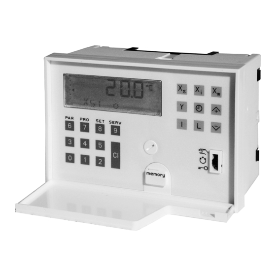
- Page 3 . . . Numerical keys Setpoint Actual value Control parameters Control deviation SERV Positioning signal Service Input Clear Limit Date and time Weekly programme Forwards Backwards and minus sign Time, date... B09791 Information centre Sauter Components 7000928003 R4...
- Page 4 Sauter Components 7000928003 R4...
-
Page 5: Table Of Contents
Target of limit ........................36 Load memory........................37 Delay time of limit......................... 37 Follow-up time for limit ......................37 Limit Y..........................37 Changeover criterion ......................37 Model number........................38 nXi3. Averaged outdoor temperature .................... 38 Sauter Components 7000928003 R4... - Page 6 SoLL Calculated setpoint based on heating curve ................42 Control deviation (standardised term)...................42 Positioning signal (standardised term) .................42 Y-0 point ..........................42 Y3. source..........................42 Calculated positioning signal ....................43 Ymin-selection / Ymax-selection ..................43 List of parameters..................................45 Appendix......................................59 Wiring diagram....................................59 Sauter Components 7000928003 R4...
-
Page 7: Service
They should be considered as examples and apply for control model 0. All entries and changes should be performed with great care. If the controller fails to work properly, the cause is often incorrect configuration, e.g. the wrong mode of action or the wrong type of transmitter. Sauter Components 7000928003 R4... - Page 8 2 - 4 Service Sauter Components 7000928003 R4...
-
Page 9: Choice Of Model; Memory; Equipment Data; Re-Start
- Switchover criterion Method 1, only based on outdoor temperature Method 2 B09372a Enter code. Only command module or heating curve are possible. If the "dry flooring" function is activated, the Automatic symbol will flash during automatic mode. Sauter Components 7000928003 R4... -
Page 10: Choice Of Model; Memory; Equipment Data; Re-Start
An 'F' in the display stands for 'Fault'. This also appears when there is an internal memory failure after a reset, e.g. due to a power failure. The controller then uses the default values and control model 0. Sauter Components 7000928003 R4... -
Page 11: How To Parameterise The Measured Value Inputs
- Start of range 100,0%r.H. bXi4 - End of range Unit of measurem. Fixed value range -30,0...150,0 °C and Ni1000 0,0...100,0 %, %r.H., kJ/kg 0,0...20,0 g/kg B09374b Enter code. Also insert jumper at rear of unit. Sauter Components 7000928003 R4... -
Page 12: How To Parameterise The Measured Value Inputs
10,0°C - Maximum value (PI 1) rXs1 45,0°C -30,0...150,0°C 15,0°C 0,0...100,0%, % r.H. - Minimum value Xs3,4 rXs3 - Maximum value (PI 2) 0,0...20,0 g/ kg rXs3 22,0°C 0,0...100,0 kJ/ kg -4999...+4999 B09376a Enter code. Sauter Components 7000928003 R4... -
Page 13: How To Set The Control Action And The Mode Of Action
B09377a Neutral zone Input Neutral zone 0,0°C - Controller 1 (PI 1) 0,0...150,0°C 0,0...100,0%, % r.H. 0,0°C - Controller 2 (PI 2) 0,0...20,0 g/kg 0,0...100,0kJ/kg 0,0% - Controller 4, 0...4999 limiter (PI 4) B09378 Enter code. Sauter Components 7000928003 R4... - Page 14 Minimum selection - From the calculated outputs Input No selection Selection from: Yc1 + Yc2 Yc1 + Yc3 Yc2 + Yc4 Yc3 + Yc4 B09379a Enter code. If Yc2 is not linked by selection, Yc2 = Y2. Sauter Components 7000928003 R4...
-
Page 15: How To Parameterise The Constant Control Outputs, Blocking Protection
- Positioning signal Y2 - Positioning signal Y3 B09380a if on: 2 07:10 on 2 07:12 off if on: 2 07:12, if Y. > 90 %, Y –10 % 2 07:14, if Y. < 90 %, Y +10 % Sauter Components 7000928003 R4... -
Page 16: Limit Value Functions
Output for setpoint change-over - Target relay rEL 2 Rel 1 Relay 1 Alerting Rel 2 Relay 2 ..- Target relay ALErt Rel 6 Relay 6 no assignment B09381a Enter code. Sauter Components 7000928003 R4... -
Page 17: Clock Function
Service 2 - 13 Clock function Clock Input - Correct running accuracy Enter deviation -199...199 s in seconds/month B09382 Enter code. Sauter Components 7000928003 R4... - Page 18 2 - 14 Service Sauter Components 7000928003 R4...
-
Page 19: Overview Of Models
Overview of models 2 - 15 Overview of models Sauter Components 7000928003 R4... -
Page 20: Description Of Functions: Rdt 300
– shift output can be parameterised, e.g. to room controllers – week clock with automatic summer/winter time switchover Sauter Components 7000928003 R4... -
Page 21: Block Diagram Rdt 300 Model 0
Overview of models 2 - 17 Block diagram RDT 300 Model 0 Sauter Components 7000928003 R4... -
Page 22: Description Of Functions: Rdt 300
– operating mode changeover: internal, or by external system remote control, off mode with frost protection – flooring function as per DIN 4725 part 4 – valve anti-jamming function – pump blocking protection – shift output can be parameterised, e.g. to room controllers – week clock with automatic summer/winter time switchover Sauter Components 7000928003 R4... -
Page 23: Block Diagram Rdt 300 Model 1
Overview of models 2 - 19 Block diagram RDT 300 Model 1 Sauter Components 7000928003 R4... -
Page 24: Description Of Functions: Rdt 300
– pump blocking protection – active dewpoint prevention using dewpoint controller (limiter), internal dewpoint calculation, optional active dewpoint input – shift output can be parameterised, e.g. to room controllers – week clock with automatic summer/winter time switchover Sauter Components 7000928003 R4... -
Page 25: Block Diagram Rdt 300 Model 2
Overview of models 2 - 21 Block diagram RDT 300 Model 2 Sauter Components 7000928003 R4... -
Page 26: Description Of Functions: Rdt 300
– shift output can be parameterised, e.g. to room controllers – week clock with automatic summer/winter time switchover Sauter Components 7000928003 R4... -
Page 27: Block Diagram Rdt 300 Model 3
Overview of models 2 - 23 Block diagram RDT 300 Model 3 Sauter Components 7000928003 R4... -
Page 28: Description Of Functions: Rdt 300
– pump blocking protection – active dewpoint prevention using dewpoint controller (limiter), internal dewpoint calculation, optional active dewpoint input – shift output can be parameterised, e.g. to room controllers – week clock with automatic summer/winter time switchover Sauter Components 7000928003 R4... -
Page 29: Block Diagram Rdt 300 Model 4
Overview of models 2 - 25 Block diagram RDT 300 Model 4 Sauter Components 7000928003 R4... -
Page 30: Description Of Functions: Rdt 300
– shift output can be parameterised, e.g. to room controllers – week clock with automatic summer/winter time switchover Sauter Components 7000928003 R4... -
Page 31: Block Diagram Rdt 300 Model 5
Overview of models 2 - 27 Block diagram RDT 300 Model 5 Sauter Components 7000928003 R4... -
Page 32: Description Of Functions: Rdt 300
– shift output can be parameterised, e.g. to room controllers – week clock with automatic summer/winter time switchover Sauter Components 7000928003 R4... -
Page 33: Block Diagram Rdt 300 Model 6
Overview of models 2 - 29 Block diagram RDT 300 Model 6 Sauter Components 7000928003 R4... - Page 34 2 - 30 Overview of models Sauter Components 7000928003 R4...
-
Page 35: Description Of Parameters
Description of parameters 2 - 31 Description of parameters Sauter Components 7000928003 R4... - Page 36 2 - 32 Description of parameters Sauter Components 7000928003 R4...
-
Page 37: Description Of Parameters
Parameter for issuing an alarm. If a short circuit is detected at input Xi6, e.g. due to a closed relay, then the output relay - which is selected using the ALErt parameter - will be closed. This makes it possible to forward an alarm. Sauter Components 7000928003 R4... -
Page 38: Bxi. , Bxi
Active dewpoint input, only Xi4 cXs. Calculated setpoint Access: manual, automatic Calculated setpoint, e.g. for summer compensation. The setpoint cXs is calculated from setpoint Xs, shifted by amount It has an adding or subtracting effect, depending on the configuration. Sauter Components 7000928003 R4... -
Page 39: Unit Of Measurement Xi
End parameter, then the value of the End parameter is used in order to control the flow temperature. End of shift Access: Manual This determines the end point of the shift on the command module. Also see FP and Sauter Components 7000928003 R4... -
Page 40: Fp Start Of Shift
Specifies the source for the limit value module. The "Off" setting completely deactivates the limit value module. Switching point for Limit Access: Manual, automatic Target of limit Access: Service level Specifies the target relay for the alarm output. If set to "Off", no relay is assigned. Sauter Components 7000928003 R4... -
Page 41: Lme
Service level Specifies the switchover criterion for the changeover function (heating or cooling mode). Method 1: based on outdoor temperature. Method 2: specified as a function of the outdoor temperature, interrogation time, changeover difference and minimum runtime Sauter Components 7000928003 R4... -
Page 42: Mod Model Number
Specifies the maximum input value for controllers 1+2, separately. The inputted value must be larger than or equal to rXs . If parameters rXs and rXs are set to the same value, no Xs adjustment is possible. Parameter rXs1 acts as a maximum limitation of the flow temperature on the heating curve. Sauter Components 7000928003 R4... -
Page 43: Range (Setpoint Range) Xs
(with preceding mathematical signs), a shift is possible in all 4 quadrants. See also .FP and .F1. Slope of heating curve Access: Manual, automatic Definition: SL= flow temperature/ outdoor temperature. Write into memory Access: Service level Writes (copies) the controller's parameters in the external parameter memory. Sauter Components 7000928003 R4... -
Page 44: St Start Value For The Flow Temperature When The Etf Is On
The command module's control action. The command module has a shift effect on the active setpoint. In conjunction with the parameters FP and F1 (with preceding mathematical signs), a shift is possible in all 4 quadrants. Sauter Components 7000928003 R4... -
Page 45: Actual Value (Standardised Term)
Proportional band (standardised term) Access: Manual Control action: controller Xp Access: Service level to set the controller's control action. provides control action A (works directly); provides control action B (works inversely). Setpoint (standardised term) Access: Manual, Automatic Sauter Components 7000928003 R4... -
Page 46: Xsf Setpoint With Risk Of Frost
Output Y3 can be used as a measuring amplifier. This parameter determines the input and is used (for example) to transmit the actual value. If (for example) a P-controller is parameterised accordingly, it can also be configured as a simple anti-frost system. Sauter Components 7000928003 R4... -
Page 47: Yc. Calculated Positioning Signal
Positioning signals Yc2 and Yc3 are only available if they are linked by selection. Maximum selection can also be achieved by externally connecting control outputs in parallel. By connecting an EXG100 active potentiometer in parallel with a control out- put, the minimum fresh-air content (for example) can be set externally. Sauter Components 7000928003 R4... - Page 48 2 - 44 Description of parameters Sauter Components 7000928003 R4...
-
Page 49: List Of Parameters
List of parameters 2 - 45 List of parameters Sauter Components 7000928003 R4... - Page 50 2 - 46 List of parameters Sauter Components 7000928003 R4...
- Page 51 List of parameters, RDT 300 Code Parameter Range Level Operating key Default value Value Model Control model number 0...6 SERV Remote control – activation On/Off SERV Copy values to controller – SERV Copy values to memory – SERV Software version –...
- Page 52 Code Parameter Range Level Operating key Default value Value Model Input 2 Flow temperature – cooling (for models 0, 1, 2, 3 and 4, parallel connection of sensor Xi1) Actual value Depends on trans- mitter and unit of meas’m’t cXi2 Type of transmitter 1 - Ni 1000 2 - 0...10 V...
- Page 53 Code Parameter Range Level Operating key Default value Value set Model Input 3 Outdoor temperature Actual value Depends on transmitter and unit of meas’m’t cXi3 Type of transmitter 1 - Ni 1000 2 - 0...10 V 3 - 2...10 V Note code plug position 4 - 0...20 mA 5 - 4...20 mA...
- Page 54 Code Parameter Range Level Operating key Default value Value Model Input 4 Humidity for dewpoint calculation or active dewpoint sensor Actual value Depends on transmitter and unit of meas’m’t cXi4 Type of transmitter 1 - Ni 1000 2 - 0...10 V 3 - 2...10 V Note code plug position 4 - 0...20 mA...
- Page 55 Code Parameter Range Level Operating key Default value Value Model Command module 1 Cooling, target depends on model Source if active target is fixed PI 2 Off, Xi1...6 SERV Control action Start of shift – 32.0 °C End of shift –...
- Page 56 Code Parameter Range Level Operating key Default value Value Model Controller 1 (PI 1) Heating Neutral zone -30.0...150.0 °C 0.0 °C Direction of operation Xp1 Main setpoint Depends on transmitter 20.0 °C and unit of meas’m’t Setback setpoint Depends on transmitter 16.0 °C and unit of meas’m’t Frost protection setpoint...
- Page 57 Code Parameter Range Level Operating key Default value Value Model Controller 3 (PI 3) Auxiliary controller for cascade Direction of operation Xp3 Proportional band 0.1...250 °C 10.0 °C Integral action time 0...9999 s 180 s rXSc Lower setpoint limit -30.0...150.0 °C 14.0 °C rXSc Upper setpoint limit...
- Page 58 Code Parameter Range Level Operating key Default value Value Model Positioning signal Y1 Limitation 0.0...100.0 % 0.0 % Limitation value Positioning signal 0...100 % Calculated positioning signal – Anti-jamming function for regulating unit On/Off Positioning signal Y2 Limitation 0.0...100.0 % 0.0 % Limitation value Positioning signal...
- Page 59 Code Parameter Range Level Operating key Default value Value Model Anti-jamming function for relays Relay 1 On/Off Relay 2 On/Off Relay 3 On/Off Relay 4 On/Off Relay 5 On/Off Relay 6 On/Off Operating modes Choice of operating mode Auto/Cooling/Heating/ Auto Off with frost moni- toring Time channel...
- Page 60 Code Parameter Range Level Operating key Default value Value set Model Limit value 2 Cooling circulation pump Assignment of source – Target relay Rel. 1...6 Rel. 4 Limit value see Xs 5.0 % Hysteresis see Xs 4.0 % Delay time 0...9999 s Follow-up time 0...9999 s...
- Page 61 Code Parameter Range Level Operating key Default value Value Model Change-over MCO =1 =2 Change-over criterion 1 – based on outdoor SERV temp. 2 - based on outdoor temp., limit value and time criterion Assignment of source – c-Od1 x Target relay 1 –...
- Page 62 Code Parameter Range Level Operating key Default value Value Model Floor-drying function Activate On/Off SERV Start temperature 10.0...40.0 °C 15.0 °C Final temperature (switch off) 25.0...60.0 °C 25.0 °C Temperature increase per day 0.0...10.0 °C 5.0 °C Clock functions Xs_ - - -:- - Setpoint change-over for contr.
-
Page 63: Appendix
List of parameters 2 - 59 Appendix Wiring diagram Input X1... X3 RDT 300 F001 0(2)...10V 0(4)...20mA 0...1V X4 X3 X2 X1 Ni1000 Ri=100k Ri=50 Ri=500k Ni1000 0...1 V 0...10 V 0...20 mA 230~ Input X4 Input X5; X6 0...10V... - Page 64 List of parameters 2 - 60 Printed in Switzerland Right of amendment reserved N.B.: A comma between cardinal numbers denotes a decimal point © Fr. Sauter AG, CH-4016 Basle Sauter Components 7000928003 R4...
Need help?
Do you have a question about the RDT 300 F001 and is the answer not in the manual?
Questions and answers