
Summary of Contents for iSMA SfAR-S-6RO
- Page 1 SfAR-S-6RO User Manual Expansion Module - 6 Relay Outputs www.ismacontrolli.com DMP271en | 3rd Issue rev. 2 | 05/2022...
-
Page 2: Table Of Contents
SfAR-S-6RO User Manual Table of Contents Introduction ..........................3 Revision History..........................3 Safety Rules..........................4 Module Features........................5 Purpose and Description of the Module ...................5 Technical Specification ........................5 Dimensions ............................6 Communication........................7 Grounding and Shielding.......................7 Network Termination........................7 Setting Module Address in RS485 Modbus Network .............7 Types of Modbus Functions......................9... -
Page 3: Introduction
SfAR-S-6RO User Manual 1 Introduction Thank you for choosing our product. This manual will help you with proper handling and operating of the device. The information included in this manual have been prepared with utmost care by our professionals and serve as a description of the product without incurring any liability for the purposes of commercial law. -
Page 4: Safety Rules
SfAR-S-6RO User Manual 2 Safety Rules • Improper wiring of the product can damage it and lead to other hazards. Make sure that the product has been correctly wired before turning the power on. • Before wiring or removing/mounting the product, make sure to turn the power off. -
Page 5: Module Features
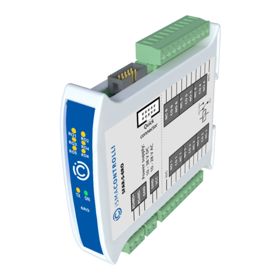
3 Module Features 3.1 Purpose and Description of the Module The SfAR-S-6RO module is an innovative device that provides a simple and cost effective extension of the number of lines of output with high current-carrying capacity. The module has 6 relay outputs. Each relay has three terminals: common (COM), normally open (NO), or normally closed (NC), which makes the unit very flexible. -
Page 6: Dimensions
SfAR-S-6RO User Manual Size Height 119.1 mm (4.689 in) Length 110.9 mm (4.366 in) Width 22.7 mm (0.894 in) Interface RS485 Up to 128 devices Table 2. Technical specification 3.3 Dimensions The appearance and dimensions of the module are shown below. The module is mounted directly to the rail in the DIN industry standard. -
Page 7: Communication
SfAR-S-6RO User Manual 4 Communication 4.1 Grounding and Shielding In most cases, I/O modules will be installed in an enclosure along with other devices, which generate electromagnetic radiation. Relays, contactors, transformers, motor controllers, etc. are examples of such devices. Radiation can induce electrical noise into both power and signal lines, as well as direct radiation into the module. - Page 8 SfAR-S-6RO User Manual Addr www.ismacontrolli.com DMP271en | 3rd Issue rev. 2 | 05/2022 page 8 of 19...
-
Page 9: Types Of Modbus Functions
SfAR-S-6RO User Manual Addr Table 3. Setting module address in RS485 Modbus network using DIP switch Setting module address in RS485 Modbus network using DIP switch 4.4 Types of Modbus Functions There are 4 types of Modbus functions supported by the SfAR modules:... -
Page 10: Restore Default Configuration
SfAR-S-6RO User Manual 4.6 Restore Default Configuration To restore the default configuration, follow the steps below: • turn the power off; • turn the DIP switch SW6 on; • turn the power on; • when power and communication LED is lit, turn the switch SW6 off. -
Page 11: Indicators
SfAR-S-6RO User Manual 5 Indicators Figure 2. Indicators Indicator Description Power Supply The LED indicates that the module is correctly powered Communication The LED lights up when the unit received the correct packet and sends the answer Outputs State The LED indicates that the output is on Table 7. -
Page 12: Connections
SfAR-S-6RO User Manual 6 Connections 6.1 Block Diagram Figure 3. Block diagram 6.2 Power Supply Connection 6.2.1 DC Power Connection Figure 4. DC power connection www.ismacontrolli.com DMP271en | 3rd Issue rev. 2 | 05/2022 page 12 of 19... -
Page 13: Ac Power Connection
SfAR-S-6RO User Manual 6.2.2 AC Power Connection Figure 5. AC power connection 6.2.3 Communication Bus Connection Figure 6. Communication bus connection 6.3 Connection of Relay Outputs 6.3.1 Connection of Resistive Load Figure 7. Connection of resistive load www.ismacontrolli.com DMP271en | 3rd Issue rev. 2 | 05/2022... -
Page 14: Connection Of Electrovalve
SfAR-S-6RO User Manual 6.3.2 Connection of Electrovalve Figure 8. Connection of electrovalve 6.4 Quick Connector The Quick Connector is an unique feature of modules that allows for quickly connecting a group of devices with a flat ribbon cable. Thanks to this solution, it is enough to connect the power supply and RS485 communication to one of the devices in the group, and the others will be powered and communicated with ribbon cable. -
Page 15: Dip Switch
SfAR-S-6RO User Manual 7 DIP Switch Figure 10. DIP switch Switch Function Description Module address +1 Setting module address from 0 to 31 Module address +2 Module address +4 Module address +8 Module address +16 Restoring default settings Restoring default settings Table 8. -
Page 16: Module Registers
SfAR-S-6RO User Manual 8 Module Registers 8.1 Registered Access Modbus Decimal Register Name Access Description Address Address Address 30001 0x00 Version/Type Read Version and type of the device 30002 0x01 Switches Read Switches state 40003 0x02 Baud Rate Read/write RS485 baud rate... -
Page 17: Bit Access
SfAR-S-6RO User Manual 8.2 Bit Access Modbus Decimal Register Name Access Description Address Address Address 0x0C0 Default Output 1 Read/write Default output 1 State state 0x0C1 Default Output 2 Read/write Default output 2 State state 0x0C2 Default Output 3 Read/write... -
Page 18: Configuration Software
SfAR-S-6RO User Manual 9 Configuration Software The SfAR Configurator is a software which is designed to set the communication module registers over Modbus network as well as to read and write the current value of other registers of the module. It is a convenient way to test the system as well as to observe real-time changes in the registers. - Page 19 SfAR-S-6RO User Manual Figure 12. The SfAR Configurator www.ismacontrolli.com DMP271en | 3rd Issue rev. 2 | 05/2022 page 19 of 19...
Need help?
Do you have a question about the SfAR-S-6RO and is the answer not in the manual?
Questions and answers