
Summary of Contents for Endress+Hauser RLN42
- Page 1 Products Solutions Services BA02065K/09/EN/01.20 71526790 2020-12-17 Operating Instructions RLN42 Two-channel NAMUR isolating amplifier with universal power supply and relay signal output...
-
Page 2: Table Of Contents
12.10 Ordering information ....24 Product description RLN42 ....7 12.11 Accessories . -
Page 3: About This Document
RLN42 About this document About this document Document function These Operating Instructions contain all the information that is required in various phases of the life cycle of the device: from product identification, incoming acceptance and storage, to mounting, connection, operation and commissioning through to troubleshooting, maintenance and disposal. - Page 4 About this document RLN42 1.2.3 Electrical symbols Direct current Alternating current Direct current and alternating current Ground connection A grounded terminal which, as far as the operator is concerned, is grounded via a grounding system. 1.2.4 Symbols in graphics 1, 2, 3,...
-
Page 5: Basic Safety Instructions
RLN42 Basic safety instructions Basic safety instructions Requirements for the personnel The personnel for installation, commissioning, diagnostics and maintenance must fulfill the following requirements: ‣ Trained, qualified specialists must have a relevant qualification for this specific function and task. ‣... -
Page 6: Product Safety
Basic safety instructions RLN42 ‣ Use only original spare parts and accessories from the manufacturer. Hazardous area To eliminate danger to persons or the facility when the device is used in the hazardous area (e.g. explosion protection): ‣ Check the nameplate to verify if the device ordered can be put to its intended use in the hazardous area. -
Page 7: Product Descriptions
(www.endress.com/deviceviewer): all data relating to the device and an overview of the Technical Documentation supplied with the device are displayed. • Enter the serial number on the nameplate into the Endress+Hauser Operations App or scan the 2-D matrix code (QR code) on the nameplate with the Endress+Hauser Operations App: all the information about the device and the technical documentation pertaining to the device is displayed. -
Page 8: Scope Of Delivery
Firmware version and device revision Approval logos 2 lines for the TAG name 4.2.2 Name and address of manufacturer Name of manufacturer: Endress+Hauser Wetzer GmbH + Co. KG Address of manufacturer: Obere Wank 1, D-87484 Nesselwang Model/type reference: RLN42 Scope of delivery The scope of delivery comprises: •... -
Page 9: Storage And Transport
RLN42 Installation 4.4.1 Functional safety A SIL version of the device is optionally available. It can be used in safety equipment in accordance with IEC 61508 up to SIL 2. Please refer to Safety Manual FY01035K for the use of the device in safety instrumented systems according to IEC 61508. -
Page 10: Disassembling The Din Rail Device
Installation RLN42 A0041736 2 Installing on DIN rail 1. Position the top DIN rail groove at the top end of the DIN rail. 2. While holding the front of the device horizontally, lower it until you hear the locking clip of the device click into place on the DIN rail. -
Page 11: Electrical Connection
RLN42 Electrical connection Electrical connection Connection conditions A flat-blade screwdriver is required to establish an electrical connection to screw or push- in terminals. AWG 24-14 AWG 24-14 0,2 -2,5 mm ² 0,2 - ,5 mm ² (0,39") 7 mm (0,28") -
Page 12: Quick Wiring Guide
Electrical connection RLN42 Quick wiring guide 24..230V AC/DC A0043438 5 Terminal assignment RLN42 Supply voltage The modules are supplied with 24 to 230 V via terminals 1.1 and 1.2. AC/DC Post-connection check Device condition and specifications Notes Are the device or cables free from damage (visual... -
Page 13: Operation Options
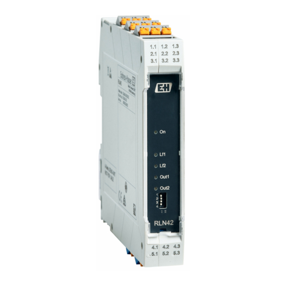
RLN42 Operation options Operation options Display and operating elements A0043446 6 Display and operating elements Plug-in screw or push-in terminal Green LED "On", power supply Red LED "LF1", line fault of sensor cable 1 Red LED "LF2", line fault of sensor cable 2 Yellow LED "OUT1", status relay 1... -
Page 14: Commissioning
Commissioning RLN42 If a line fault occurs, the relay is de-energized and the red LED "LF" flashes (NE 44). NOTICE Error detection malfunctions ‣ For switch contacts with an open circuit, line fault detection (LF) must be disabled or the corresponding resistance circuit (1 kΩ/10 kΩ) must be provided directly at the contact. -
Page 15: Switching On The Device
RLN42 Commissioning NOTICE ‣ Before commissioning the device, make sure that the supply voltage matches the voltage specifications on the nameplate. Failure to perform these checks may result in damage to the device caused by the incorrect supply voltage. Switching on the device Switch on supply voltage. -
Page 16: Diagnostics And Troubleshooting
Diagnostics and troubleshooting RLN42 Diagnostics and troubleshooting General troubleshooting Always start troubleshooting with the checklists below if faults occur after startup or during operation. The checklists take you directly (via various queries) to the cause of the problem and the appropriate remedial measures. -
Page 17: Return
RLN42 Repair 11.3 Return The requirements for safe device return can vary depending on the device type and national legislation. 1. Refer to the website for more information: http://www.endress.com/support/return-material 2. Return the device if repairs or a factory calibration are required, or if the wrong device was ordered or delivered. -
Page 18: Technical Data
RLN42 Technical data 12.1 Function and system design Product description RLN42 Product design NAMUR isolating amplifier • The NAMUR isolating amplifier is designed for the operation of proximity switches (according to EN 60947-5-6 (NAMUR)) and open and mechanical contacts with resistive coupling elements. -
Page 19: Power Supply
Power supply Terminal assignment Quick wiring guide 24..230V AC/DC A0043438 7 Terminal assignment RLN42 Supply voltage The modules are supplied with 24 to 230 V via terminals 1.1 and 1.2. AC/DC Important connection data Power supply Supply voltage range... -
Page 20: Performance Characteristics
Technical data RLN42 AWG 24-14 AWG 24-14 0,2 -2,5 mm ² 0,2 - ,5 mm ² (0,39") 7 mm (0,28") 0,5-0,6 Nm 5-7 lb In A0040201 8 Electrical connection using screw terminals (left) and push-in terminals (right) Terminal design... -
Page 21: Environment
RLN42 Technical data A0041736 9 Installing on DIN rail 1. Position the top DIN rail groove at the top end of the DIN rail. 2. While holding the front of the device horizontally, lower it until you hear the locking clip of the device click into place on the DIN rail. -
Page 22: Mechanical Construction
Technical data RLN42 12.8 Mechanical construction Design, dimensions Dimensions in mm (in) Terminal housing for mounting on DIN rail A0044417 Width (B) x length (L) x height (H) (with terminals): 17.5 mm (0.69 in) x 116 mm (4.57 in) x 107.5 mm (4.23 in) -
Page 23: Display And Operating Elements
RLN42 Technical data 12.9 Display and operating elements A0043446 10 Display and operating elements Plug-in screw or push-in terminal Green LED "On", power supply Red LED "LF1", line fault of sensor cable 1 Red LED "LF2", line fault of sensor cable 2 Yellow LED "OUT1", status relay 1... -
Page 24: 12.10 Ordering Information
Technical data RLN42 NOTICE Error detection malfunctions ‣ For switch contacts with an open circuit, line fault detection (LF) must be disabled or the corresponding resistance circuit (1 kΩ/10 kΩ) must be provided directly at the contact. ( See the "Quick wiring guide" and "Accessories" sections of the Operating... -
Page 25: 12.11 Accessories
Various accessories, which can be ordered with the device or subsequently from Endress +Hauser, are available for the device. Detailed information on the order code in question is available from your local Endress+Hauser sales center or on the product page of the Endress+Hauser website: www.endress.com. -
Page 26: 12.13 Supplementary Documentation
• W@M Device Viewer (www.endress.com/deviceviewer): Enter the serial number from nameplate • Endress+Hauser Operations App: Enter the serial number from the nameplate or scan the 2D matrix code (QR code) on the nameplate Brief Operating Instructions Guide that takes you quickly to the 1st measured value... -
Page 27: Appendix: System Overview Of Rn
Read the information leaflet enclosed in the package of the individual products. 13.1.2 Power supply options RN4x Series (24 to 230 V) The RN42 active barrier and the RLN42 NAMUR isolating amplifier are available with an extended supply voltage range of 24 to 230 V . These modules are powered... - Page 28 • NAMUR isolating amplifier • Output isolating amplifier 13.2.2 RLN42 NAMUR isolating amplifier The NAMUR isolating amplifiers isolate and convert the analog NAMUR signal of connected proximity or limit switches to binary relay output states. The abbreviation "NAMUR" is based on the former association name "Normen Arbeitsgemeinschaft für Mess- und Regeltechnik in der chemischen Industrie...
- Page 29 RLN42 Appendix: system overview of RN Series proof. A short-circuit and line break in the sensor line can be detected by the RLN42 evaluating unit. A NAMUR sensor does not need a separate power supply: its power is supplied via the measuring circuit.
- Page 30 Appendix: system overview of RN Series RLN42 FTE20 RLN42 Resistive coupler Output Input (binary) (1.2 or 2.1 mA) Power supply 24 - 230 V AC/DC A0045924 13 NAMUR limit detection with FTE20 paddle switch with line monitoring in the hazardous area...
-
Page 31: Index
RLN42 Index Index Accessories Device-specific ......25 CE mark ........6 Declaration of Conformity . - Page 32 *71526790* 71526790 www.addresses.endress.com...
Need help?
Do you have a question about the RLN42 and is the answer not in the manual?
Questions and answers