Advertisement
Quick Links
Advertisement

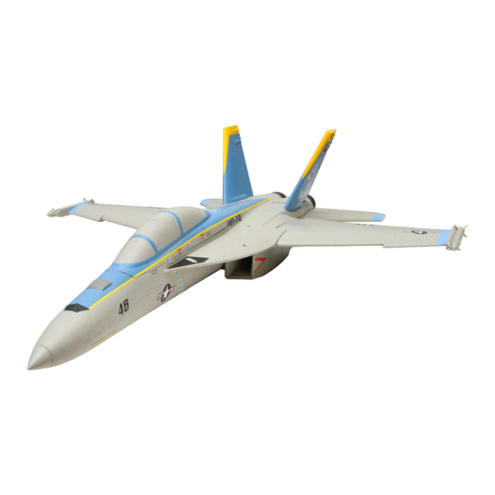
Summary of Contents for H-KING F-18 50MM EDF 4S
- Page 1 INSTRUCTION MANUAL H - KING F - 18 50MM EDF 4S WITH ORX FLIGHT STABILIZER...
- Page 2 • This is a radio controlled flying model and as such must always be flown with caution, this is NOT a toy. • The H-King brief was to design a model for low hours to intermediate pilots. • Always exercise great caution when using the recommended battery to power this product. For full safety notes and operating procedures please read the information provided by your battery supplier.
- Page 3 SPECIFICATION - Length: 800mm - ESC: 30A with BEC - Servo: 4 x 9g - Wing span: 588mm - Weight w/battery: 4S Li-Po 1300 mAh (500g +/-10g) - Power: 50mm EDF 4S high power brushless motor. - Radio: Radio: 6ch and up with electronic mixing capability computer radio (Recommended) - Battery: 1000-1300 mAh 4S Li-Po 30-60C (Recommended)
- Page 4 CONTENTS 1. Fuselage 2. Canopy 3. Main wing set 4. Vertical fin 5. Horizontal stabilizer 6. Nose cone 7. Carbon fiber wing joiner 8. Pushrods 9. Double sided tape...
- Page 5 ASSEMBLY INSTRUCTIONS MAIN WING 1. Pass the supplied carbon fiber wing joiner through the fuselage 2. Install the right wing onto the fuselage and connect the wing servo lead. Then gently push the wing against the fuselage until it hits the magnet on the wing saddle.
- Page 6 HORIZONTAL STABILIZER 1. Get the Left/Right stabilizer parts ready. Apply foam safe glue to the root of the stabilizer and install the left hand side stab onto the fuselage tail as shown. 2. Repeat the above steps for the right-hand side horizontal stabilizer. 3.
- Page 7 NOSE CONE Use a foam safe glue to attach the nose cone. YOUR F-18 BUILD IS COMPLETE...
- Page 8 C OF G POSITION The C of G is 48-53 mm from the wings leading edge. For first flights we recommend you use the forward measurement. Once you get used to the model you can then move it back, do not though exceed the most rearward measurement.
- Page 9 F-18 ORX FLIGHT STABILISATION SYSTEM FEATURES • Integrated with a 32bit MCU and a 6 axis digital gyro for ultra fast flight control response. • The ORX stabilisation device is tuned specifically to a particular model for the best flying performance. •...
- Page 10 PUSHROD LINKAGES SETUP Connect the ORX via one of the PWM/PPM/SBUS inputs of your chosen receivers. Connect a 4S Li-Po battery pack and switch on your TX to prepare to set the throws of the control surfaces. Ensure the servo horns on all servo output shafts are perpendicular to servo cases, and all control surfaces are perfectly level.
- Page 11 TX AND ORX STABILISATION DEVICE SETUP Note: If you wish to set up Expo/Dual rates on the elevator and aileron channels to meet your flying style, you must set them only under the Intermediate and Expert flight mode. SWITCH ON THE TX Place your F-18 50mm EDF on level ground.
- Page 12 LED INDICATION STATUS • LED light off (No radio signal) • LED light turns solid (Beginner mode) • LED light flashes quickly (Intermediate mode) • LED light flashes slowly (Expert mode) To arm the stabilization system you need to open the throttle to a low setting for 1 or 2 seconds then close the throttle.
- Page 13 RC CONTROL Roll Left: Move the aileron stick to the left, the left aileron should go up. Roll Right: Move the aileron stick to the right, the right aileron should go up. Pitch Up: Move the elevator stick down, the elevator should go up. Pitch Down: Move the elevator stick up, the elevator should go down.
- Page 14 GYRO CONTROL 1. You now need to check that the gyro is functioning correctly. 2. Move the gyro switch down into the "Training Mode", this is the switch in the fully down position. Now smartly roll the wings left and right, you should then see the ailerons moving in the opposite direction to the rolling moment.
- Page 15 TROUBLE SHOOTING Problem Cause Solution Charge the batteries. Batteries not fully Install a charged battery. charged. Check connection Transmitter battery low. between the ESC and motor. Replace motor. Motor not connected. Motor does not Consult adio manual and The motor is damaged. go through bind procedure again.
- Page 16 RECOMMEND BATTERY PACK Turnigy Nano-Tech Plus 1000 mAh Turnigy Graphene Panther 1000 mAh 4S 70C Lipo Pack w/XT60 4S 75C Battery Pack SKU:9210000262-0 SKU:9067000360-0 Turnigy nano-tech 1000 mAh 4S Turnigy 1300 mAh 4S 60C Lipo 45~90C Lipo Pack Pack w/XT60 SKU:N1000.4S.45 SKU:9067000520-0...
- Page 17 REPLACEMENT SPARE PARTS...
- Page 18 APEX CE SPECIALISTS LIMITED UK REP 89 Princess Street, Manchester, M1 4HT, UK APEX CE SPECIALISTS LIMITED Unit 3D North Point House, North Point Business Park, New Mallow Road, Cork, T23 AT2P, Ireland...
Need help?
Do you have a question about the F-18 50MM EDF 4S and is the answer not in the manual?
Questions and answers