Table of Contents
Advertisement
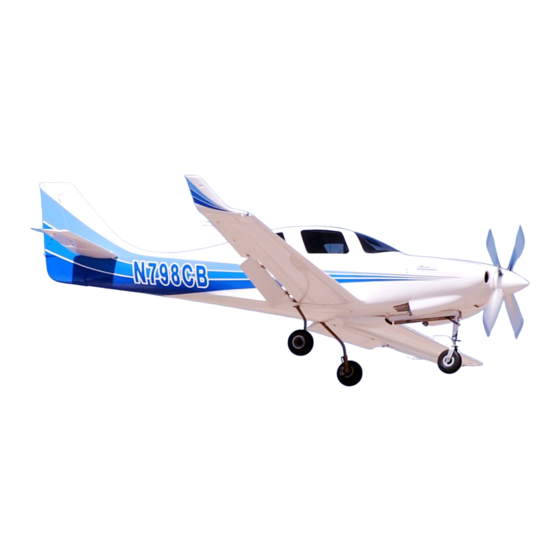
Lancair IV
HANDBOOK TABLE OF CONTENTS
SECTION
I
GENERAL
SECTION
II
LIMITATIONS
SECTION
III
EMERGENCY PROCEDURES
SECTION
IV
NORMAL PROCEDURES
SECTION
V
WEIGHT AND BALANCE
SECTION
VI
SYSTEMS DESCRIPTION
SECTION
VII
HANDLING, SERVICE and
MAINTENANCE
SECTION
VIII
SUPPLEMENTS
2
11
16
23
33
37
48
60
General
Section I
Table of Contents
IMPORTANT NOTICE
REVISING THIS HANDBOOK
DESCRIPTIVE DATA
Engines
Propellers
Fuels
Oil Capacities
Weights
Cabin and Entry Dimensions
Baggage
Specific Loading (Max Take-off Weight)
GEN. AIRSPEED
TERMINOLOGY/SYMBOLS
METEROLOGICAL TERMINOLOGY
POWER TERNINOLOGY
ENGINE CONTROLS/INSTRUMENTS
PERFORMANCE AND
FLIGHT PLANNING TERMINOLOGY
WEIGHT AND BALANCE TERMINOLOGY
3
4
5
6
7
7
8
8
9
Advertisement
Chapters
Table of Contents

Subscribe to Our Youtube Channel
Related Manuals for Lancair IV


Summary of Contents for Lancair IV
- Page 1 Lancair IV General Section I HANDBOOK TABLE OF CONTENTS SECTION Table of Contents GENERAL IMPORTANT NOTICE SECTION REVISING THIS HANDBOOK LIMITATIONS DESCRIPTIVE DATA Engines SECTION Propellers EMERGENCY PROCEDURES Fuels Oil Capacities SECTION Weights Cabin and Entry Dimensions NORMAL PROCEDURES Baggage...
- Page 2 Lancair. tion equal to that of its original manufacture. Authorized Service Facilities can provide recommended service, repair, or operating procedures IMPORTANT NOTICE issued by both the FAA and Lancair International to ob- tain the maximum prudent usefulness and safety from your Lancair. This handbook must be read carefully by the owner or operator(s) of your Lancair in order to become familiar with its operation and to obtain all it has to offer in terms of both speed and reliability. Herein are...
- Page 3 In an effort to provide as complete coverage as possi- of their Lancair with any optional equipment installed. ble, some optional equipment has been included in the scope of this handbook. However due to the variety REVISING THIS HANDBOOK of airplane configurations available, some equipment...
- Page 4 46 inches PROPELLERS rear seat 43 inches The Lancair IV uses a MT , 76”, 3 bladed con- stant speed propeller. Propeller governors are made by BAGGAGE Compartment Volume McCauley, Lancair PN. D20309-39. Approx. 13.5 Cu. Ft. Lancair is constantly testing other propellers that may...
- Page 5 SPECIFIC LOADING (max take-off weight) Wing loading Maximum Flap Extend Speed is the highest 32.65 lb./sq. ft. speed permissible with wing flaps in a prescribed ex- Power loading (350 h.p.) tended position. 9.14 lb./h.p. Maximum Landing Gear Extended Speed is the maximum speed at which an airplane can be safely GENERAL AIRSPEED TERMINOLOGY flown with the landing gear extended. AND SYMBOLS Maximum Landing Gear Operating Speed is the maximum speed at which the landing gear can be safely CAS Calibrated Airspeed is the indicated speed of an extended or retracted. airplane, corrected for “position error” and instrument error.
- Page 6 AND SYMBOLS flown with the landing gear extended. Maximum Landing Gear Operating Speed is the CAS Calibrated Airspeed is the indicated speed of an maximum speed at which the landing gear can be safely airplane, corrected for “position error” and instrument extended or retracted. error. Calibrated airspeed is equal to true airspeed in standard atmosphere at sea level. Never Exceed Speed is the speed limit that may not be exceeded at any time. Ground Speed is the speed of an airplane rela- tive to the ground.
- Page 7 GPH Gallons per hour fuel flow. PPH Pounds per hour fuel flow.
- Page 8 International Standard Atmosphere in which winds. 1) The air is a dry perfect gas; 2) The temperature at sea level is 15 Celsius POWER TERMINOLOGY Fahrenheit); 3) The pressure at sea level is 29.92 in. Hg. Take-off and Maximum Continious The highest pow- (1013.2 millibars); er rating not limited by time. 4) The temperature gradient from sea level to the altitude at which the outside air Cruise Climb The power recommended for cruise temperature is -56.5 C (-69.7 F) is- 0.00198...
- Page 9 The value shown is considered to be limiting. The value in this handbook is that demonstrated by Lancair test pilots and considered safe. MEA Minimum enroute IFR altitude. Route Segment A part of a route. Each end of that part is identified by: 1) a geographical location; or...
- Page 10 Its distance proved for the start of the take-off run. The value shown is considered to be limiting. The value from the reference datum is found by dividing the total in this handbook is that demonstrated by Lancair test moment by the total weight of the airplane. Maximum Landing Weight Maximum weight ap- pilots and considered safe.
-
Page 11: Table Of Contents
Section II The data approved by Lancair International and Table of Contents the limitations presented herein are those established by Lancair as applicable to the Lancair IV model aircraft. GENERAL The airspeeds quoted are given conventional nomen- clature, are shown in knots, calibrated airspeed, and AIRCRAFT OPERATING SPEEDS assumes zero instrument error. -
Page 12: Powerplant Limitations
OPERATING LIMITATIONS Operating limitations for the TSIO-550B engine is list- PROPELLERS ed below. If your engine differs, you must account for The Lancair IV uses a Hartzell or MT 3 bladed con- that. In addition, the data and limits shown are for new stant speed propeller. Propeller governors are made by specification engines and do not reflect any degradation McCauley, Lancair part # D20309-39 . due to age or number and quality of overhauls. -
Page 13: Misc Instrument Markings
POWERPLANT INSTRUMENT TURBINE INLET TEMP (Deg. F) MARKINGS Max. Continuous (Green Arc) 1750 Peak -30 Second limit (Red Line) 1800 It is recommended that the following markings be made on the engine instrument gauges to conform to conven- MANIFOLD PRESSURE (In. Hg.) tion. Operating range (Green Arc) 15-38 NOTE Maximum (Red Radial) Continental TSIO-550 B values shown. The owner/ operator should compare and correct (where differ- FUEL FLOW (PSIG) ent) for the particular model specifications for his Operating range (Green Arc) -
Page 14: Reference Datum
FLIGHT LOAD FACTOR LIMITS freezing. Flaps Up +4.4, to -2.3 g’s. Flaps Down +3.8, to -2.0 g’s TYPES OF OPERATIONS AND LIMITS The Lancair IV is approved for the following types of flight when the required equipment is installed and op- erations are conducted as defined in the LIMITATIONS section. 1. VFR, day and night 2. IFR, day ;and night Warning 1. Flight operations with passengers for hire 2. Flight into known icing is prohibited. -
Page 15: Note
Section III cated airspeeds (KIAS) and assume zero instrument error. Each aircraft should be calibrated to deter- mine its specific error for various configurations. Table of Contents A Pacer method is suggested, flying against a “known” aircraft. EMERGENCY AIRSPEEDS EMERGENCY AIRSPEEDS ENGINE FAILURE Emergency Descent (Idle Power, Gear/Flaps up 170-274... - Page 16 shallow turns to avoid obstacles. Sufficient Runway remaining: If sufficient altitude has been gained to attempt a restart: Throttle CLOSED Brakes APPLY as necessary Item Condition Stop straight ahead Airspeed 100 KTS Fuel Selector Insufficient Runway remaining: Mixture RICH Throttle CLOSED Magneto’s, Cycle, Then BOTH Brakes APPLY as necessary Boost Pump (To check for engine driven pump Mixture IDLE CUT-OFF failure,) HIGH,(momentarily) Fuel Selector Flaps (on final) FULL Master Switch Magneto’s In Flight Maintain directional control and maneuver to...
-
Page 17: Rough Running Engine
ROUGH RUNNING ENGINE Starter CONTINUE CRANKING Mixture IDLE CUT-OFF Item Throttle FULL OPEN Condition Boost pump Mixture RICH Fuel Selector OFF Boost Pump (if above 10,000’) Magneto’s, Cycle, Then BOTH EMERGENCY DECENT Mixture ADJUST NOTE Throttl IDLE Speed Brakes (If installed) DEPLOY If power is restored and there is any doubt Propeller HIGH RPM as to the cause of the engine stoppage, land at the... -
Page 18: Systems Emergencies
IFR operations. If a voltmeter is installed will be your key indicator of alternator failure which then places the entire electrical load on the battery. Propeller Overspeed The battery will read approximately 12.4/24.8 The controllable pitch propellers (with Mc Cau- volts on a full charge, and 14+/28+ on the alternator. If ley governors) used on the Lancair IV utilize oil pres- you experience alternator failure; sure from the governor to increase pitch (low RPM), Others may operate in an opposite manner. Therefore it Circuit Breakers CHECK is the responsibility; of the pilot to know his aircraft and Master Switch its system. -
Page 19: Speed Brakes
110 KIAS minimum. If the door becomes unlatched or opens in flight the first priority is to “FLY THE AIRPLANE”. If the Landing Gear door is still hooked, have a passenger hold the handle Your Lancair IV gear is held up by hydraulic to prevent further opening, if the door has completely pressure. A pressure switch shuts off the electrical opened do not attempt to close it. Slow the airplane power to the pump when system pressure (1100 psi) down to approach speed, extend the flaps and return to is achieved. -
Page 20: Emergency Speed Reduction
DESCENT - (Checklist) would be the extension of the wing flaps before reach- BEFORE LANDING - (Checklist) ing 132 KIAS (Vfe) BALKED LANDING - (Checklist) AFTER LANDING - (Checklist) SECURING THE AIRPLANE- (Checklist) LEANING ALTERNATE AIR HEATING & VENTILATION COLD WEATHER OPERATIONS ICING CONDITIONS NOISE SAFE OPERATING AIRSPEEDS Normal Procedures Section IV NOTE All airspeeds in this section are indicated airspeeds Table of Contents... - Page 21 in Knots (KIAS) and assume zero instrument or in- TANK. stallation error. You should make sure your system has been correctly calibrated and account for those EMPENNAGE errors as necessary. (1) Baggage Door — LOCKED. (2) Static Port — CLEAR. Max Demonstrated X-WIND component (3) Tail Tie-Down — DISCONNECT. Max Speed Brake Deployment Rotate Speed (Vr) with flaps 10 deg. (4) Control Surfaces — CHECK freedom of Best Angle of Climb (Vx) movement and security.
- Page 22 (6) Before first flight of the day and after are OFF and that no one is in or near the each refueling, use cockpit while performing this check. Hands pass sampler cup and drain small quantity of through the prop arc, thus if the prop turns fuel from fuel tank sump quick-drain severe injury or amputation will occur.
-
Page 23: Before Starting - (Checklist)
(3) Flap — CHECK for movement and throttle 1/4 to 1/2 open. Reduce throttle to idle when security. engine fires. (4) Main Landing Gear Door—SECURE. (8) Oil Pressure — CHECK. BEFORE STARTING NOTE (1) Preflight Inspection — COMPLETE. After starting, check for oil pressure indica- (2) Seats, Belts, Shoulder Harnesses — tion within 30 seconds in normal temperatures and ADJUST and LOCK. - Page 24 cept have mixture control idle cut-off, throttle full open, (6) Radios — SET. and electric fuel pump on high for approximately 15 to (7) Autopilot (if installed) — TEST, Then 20 seconds. STAND BY or OFF. (8) Fuel Selector Valve — FULLEST GROUND WARM-UP TANK, Teledyne-Continental aircraft engines are air- (9) Mixture—RICH. cooled and are dependent on the forward (10) Throttle — 1700 RPM. speed of the aircraft for cooling. To prevent Magnetos — CHECK (RPM overheating, it is important that the drop should not exceed 150 following rules be observed: RPM on either magneto or 50...
- Page 25 (1) Power — 22-31” Hg, 2100-2500 RPM. NORMAL TAKEOFF (2) Elevator and Rudder Trim — ADJUST. (1) Wing Flaps — 10 degrees (3) Mixture — LEAN. (2) Power — Smoothly apply FULL (4) Low Boost — As necessary for vapor THROTTLE (Max 38” Hg) and 2700 suppression. RPM. (3) Elevator Control — LIFT NOSE WHEEL at 65 KIAS. (4) Climb Speed — 110 KIAS - flaps 10 degrees (VX). 135 KIAS - flaps UP (VY). MAXIMUM PERFORMANCE TAKEOFF/CLIMB (1) Wing Flaps — 20 degrees. (2) Power — FULL THROTTLE (Max 38” Hg) and 2700 RPM. (3) Brakes — RELEASE, above 25” Hg. (4) Elevator Control — ROTATE at 65 KIAS.
- Page 26 DESCENT (3) Gear — Retract after positive rate of climb. (1) Power — AS DESIRED. (4) Airspeed — 110 KIAS (VX). (2) Low Boost - OFF. (5) Wing Flaps — RETRACT slowly. (3) Mixture — ENRICHEN as required. (4) Speed Brakes— AS DESIRED NORMAL LANDING (5) Wing Flaps — AS DESIRED (0 - 10 (1) Touchdown — MAIN WHEELS FIRST. degrees below (2) Landing Roll - Lower nose wheel slow- 174 KIAS, 10 - 40 degrees below 132 KIAS). (3) Braking — MINIMUM REQUIRED. BEFORE LANDING AFTER LANDING (1) Seats, Belts, Shoulder Harnesses — (1) Wing Flaps — UP. ADJUST and LOCK. (2) Transponder — OFF.
-
Page 27: Leaning
LEANING 1. Adjust RPM for desired cruise setting. 2. Slowly move mixture control toward “lean” CRUISE CONTROL BY PERFORMANCE while observing T.I.T. gage. Note position on CURVE the instrument where the needle “peaks” or starts to drop as mixture is leaned further. NOTE Refer to chapter 13 of the Teledyne Continen- 3. Maximum recommended cruise setting is to tal Motors Operators and Maintenance manual for be determined (TBD). -
Page 28: Alternate Air
Once these deposits have induction air. been removed (preferably by warming in a hangar) the preflight should include special emphasis on freedom of HEATING & VENTILATION control movements. Cooling air. Your Lancair is equipped with a NACA air intake scoop in the vertical stabilizer for cabin venti- ENGINE CONSIDERATIONS lation, simple eyeball vents are installed in the overhead Very cold temperatures require extra consider- to control air flow through the cabin. -
Page 29: Icing Conditions
overspeeding. During descents and landing, give spe- cial attention to cylinder head temperatures, since the engine will easily over cool. ICING CONDITIONS Flight in icing conditions is prohibited. Should ice be inadvertently encountered it can be expected that drag will increase, possibly markedly, stall speeds will increase, again possibly significantly and extreme care must be exercised while ice is present on the airframe. It is prudent to avoid icing conditions if at all possible. - Page 30 Weight & Balance GENERAL Proper CG is absolutely critical to safe flight. Section V This is where NO exceptions can be considered - you must verify that the center of weight is in the correct Table of Contents position and if it is not, you MUST correct it before flight.
- Page 31 Log these weights in the appropriate lines on Column A. (See blank Lancair IV “Weight and This empty weight CG must ultimately be for- Balance Sheets” provided for recording these data.) ward of the allowable flight CG range since when the pilot gets into the aircraft, he will be aft of this point 6. Log the weights of any shim stock (the 1 x 4s...
- Page 32 NOTE sengers, fuel and baggage. It is recommended that this The allowable Center of Gravity Range is be done as this is the most accurate means of attaining Fuselage Station (FS) 86.5 to FS 94.5 a true loading analysis for your particular airplane. If you are measuring for fuel loads, use 5.9 lbs/gallon to Before removing the aircraft from the scales, it calculate the weight)..
- Page 33 SYSTEMS DESCRIPTIONS Engine Instrumentation SECTION VI Engine Starting TABLE OF CONTENTS Accessories Fire Detection/Extinguishing GENERAL Abnormal Operation AIRFRAME PROPELLERS Materials FUEL SYSTEM FLIGHT CONTROLS HYDRAULIC SYSTEM BRAKE SYSTEM Trim Controls ELECTRICAL SYSTEM GROUND CONTROL Hydraulic Power Pack Electrical FLAPS Aircraft Lighting HEATING, VENTILATING & DEFROSTING SPEED BRAKES PILOT PRESSURE SYSTEM LANDING GEAR STATIC PRESSURE SYSTEM...
-
Page 34: General
The three trim motors are made by the various techniques and materials involved. MAC Inc. Materials GROUND CONTROL The Lancair IV is fabricated of high temperature The Lancair IV is controlled on the ground prepreg Carbon Fiber skins over a high temperature using differential braking to control the castering nose Divinycell or Nomex Honeycomb core. With the ex- gear. A little caution for the first few flights in the air-... -
Page 35: Speed Brakes
LANDING GEAR and normal hydraulic pressure help hold it there. The The Lancair IV main landing gear is constructed main gear is held in the down position by a mechanical of gun drilled tubular steel. The main gear is retracted... -
Page 36: Baggage Compartment
All baggage carried should be secured for ev- CONTROL LOCKS ery flight. Even a flight in smooth air could encounter unexpected clear air or wake turbulence or require an The normal control lock for the Lancair is the evasive maneuver which could become a hazard to use of a seat belt secured over one or both of the control the flight anywhere from a nuisance to being cata- sticks. And while we would all like to have a hangar strophic. -
Page 37: Engines
ENGINES Controllable propeller engines have a prop control which controls the engine RPM. Maximum engine RPM at full throttle General Information settings are required for takeoff. Cruise power settings reduce The Lancair IV is generally fitted with a Conti- engine RPM commensurate with manifold pressure. nental engine of 300-350 HP and a constant speed pro- Fuel/air ratio is also controlled to compensate for the peller. These engines are FAA certified aircraft power- large air density changes due to operation at altitude. This... - Page 38 Know your system and check its operation often. EGT, TIT & Engine Monitors. A measure of opti- Engine Starting mum fuel/air ratio is available by sensing the tempera- ture of the exhaust gases. Operating the engine at or Starting of the Lancair is simple. The aircraft is near its peak exhaust temperature means that you are generally equipped with an electric starter which cranks operating at the near optimum fuel/air ratio. Exhaust the engine to provide the first of the three basic require- gas temperature is kept within limits indirectly by es- ments (air, fuel and ignition). Fuel is introduced by a...
-
Page 39: Fire Detection/Extinguishing
If no voltage measurement is available, an amp meter may show discharge (-) at low Abnormal Operation RPM conditions (indicating that current for operating After a few hours of operating your Lancair the aircraft’s equipment is coming from the battery) and you will become familiar with its operation from its charge (+) at higher engine RPM’s indicating that the flight controls to the engine. It is good practice to make battery is being charged. -
Page 40: Fuel System
Steering of the aircraft on the ground is pull you through many hours of flight. by use of differential brakes. The rudder pedals incor- porate independent toe brake cylinders operating the FUEL SYSTEM “Cleveland” type disk brakes on the main gear. Brakes The standard Lancair has a very simple fuel should be checked each time you leave the ramp prior system. It feeds fuel to the engine pump through a fuel to taxiing. Care should be used to not ride the brakes selector, electric boost pump then a gascolator. Each unnecessarily by using only sufficient power to main- wing tank has a screen at its outlet. Aircraft with the... -
Page 41: Aircraft Lighting
Lancair. The avionics are operated off a separately powered avionics buss to allow the whole set of equip- ment to be turned off and on at one time. Their lighting systems are integral and with this configuration it is possible to leave on only one comm or one nav should an electrical failure occur in flight making the most effective use of the remaining battery power. -
Page 42: Heating, Ventilating & Defrosting
The vacuum system is powered by a vacuum PITOT PRESSURE SYSTEM pump driven by the engine. Its operation is vital to gyro The Lancair should be fitted with a standard instruments and is indicated by a suction gauge. The heated pitot probe typically located on the lower, out- gauge can be one which indicates the suction value, or a board side of the right wing. If your flights have the po-... - Page 43 HANDLING, SERVICING & INTRODUCTION TO SERVICING MAINTENANCE This section is designed to help you the owner and pilot of your Lancair to service and maintain it in a SECTION VII safe and efficient manner. The information is approved by Lancair International. The intended user of this TABLE OF CONTENTS handbook is the pilot, not the aircraft’s mechanic. The...
-
Page 44: Airplane Inspection Periods
FBO by becoming your of delaminations, corrosion of parts, security of fittings second pair of eyes on an as required basis. Lancair or and fasteners, a compression test of the engine’s cylin- your local EAA chapter can supply you with helpful ders and an inspection of the propeller. This “Annual information in this regard.Non-owner Built Aircraft... -
Page 45: Alterations Or Repairs
If you purchased your aircraft, your local FAA In addition there are continuing care items, items which inspector may be interested if you make any alterations. have a recommended overhaul or replacement schedule They may contact Lancair for advice. In any case, the and special inspections required due, such as gear/ flap work must be performed by properly licensed person- extensions at high speeds. nel. -
Page 46: Main Wheel Jacking
With the tion from the elements is the primary concern. With the nose wheel off the ground, the aircraft can be pivot- Lancair it may be easiest to remove the wings and store ed around the main gear as required.Tie-downs it in your garage where you have (or can provide) some control over temperature and humidity. - Page 47 cooling air intake (NACA inlet) covered or plugged, and the battery removed.
-
Page 48: Preparation For Service
Each month, the aircraft should be started and run. It overhauled engine, very long flights should be avoided is preferable to fly the aircraft for thirty (30) minutes as until it is certain that the sump quantity is sufficient for the Lancair engine compartment is tight and inadequate the flight duration. The oil level is checked through cooling may result from a ground run. the small door on the top side of the engine cowling. A... -
Page 49: Battery
WARNING a running history of the contaminates from each of your Tire size is important on your Lancair. Use oil changes. only the specified tire. Other sizes will not fit into... -
Page 50: Brakes
PROPELLER The Lancair uses a negative ground system. Your propeller should be serviced according to Filters in the system reduce noise in the avionics from... -
Page 51: Care And Cleaning
Oil and grease can be removed with cloth damp- CARE AND CLEANING ened slightly with kerosene. Volatile solvents such as Your Lancair requires no special care and clean- those mentioned for the windshield are to be avoided. ing. Prior to washing, cover the wheels, pitot and static ports and pug cabin air intake ports. Care should be... -
Page 52: Engine
DC-8s, not Lancairs. Lube landing gear mechanism Check control surface hinges ENGINE Each 100 Hours Change engine oil Clean the engine with a neutral solvent. While Change oil filter the engine is warm but not hot, spray with solvent and Clean fuel strainers allow to set a few minutes. Follow with a spray wash Hoses, wear, tightness, no cracks, and allow to dry. Avoid excessively high pressures secure Cowling attach fasteners-... - Page 53 Battery-electrolyte level and LANCAIR IV SAMPLE LOADING SHEET specific gravity Running lights and strobes- LANCAIR IV 3 VIEW operation Landing Lights-operation CONTINENTAL ENGINE EXCERPTS Cockpit lights-operation ELT-battery life, operation check LANCAIR IV PRESSURIZED Static system-leak tight, x-ponder functional SPEED BRAKES Door attach points & mecha nism-secure Door hinge pins for wear and lube Shoulder harness-attach points SUPPLEMENTS secure, fraying mat’l Seat belts-attach points secure, fraying mat’l.
Need help?
Do you have a question about the IV and is the answer not in the manual?
Questions and answers