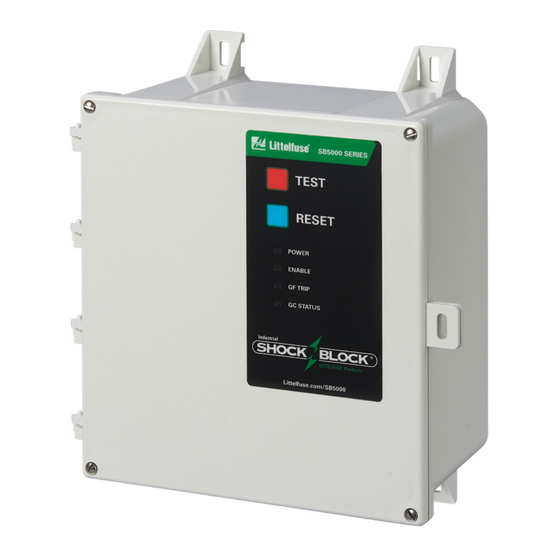

Related Manuals for Littelfuse Industrial Shock Block SB5000 Series

Summary of Contents for Littelfuse Industrial Shock Block SB5000 Series
- Page 1 Tel: +1-800-832-3873 E-mail: relays@littelfuse.com www.littelfuse.com/SB5000 SB5000 MANUAL ® INDUSTRIAL SHOCK BLOCK REVISION 1-B-101821 Copyright © 2021 by Littelfuse, Inc. All rights reserved.
- Page 2 SB5000 Industrial Shock Block Page i Rev. 1-B-101821 This page intentionally left blank.
-
Page 3: Table Of Contents
3.3.4 PWR Loss Mode (Switch 4) ......10 Specifications are subject to change without notice. 3.4 Input Connection ............ 10 Littelfuse is not liable for contingent or consequential 3.5 Undervoltage, Overvoltage and Chatter Detection 10 damages, or for expenses sustained as a result of incorrect 3.6 Temperature Limit Trip ......... - Page 4 SB5000 Industrial Shock Block Page iii Rev. 1-B-101821 This page intentionally left blank. ...
-
Page 5: Introduction
SB5000 Industrial Shock Block Page 1 Rev. 1-B-101821 3-Phase Grounded-neutral systems where voltage to NTRODUCTION ground is 150 Vac or less and equipment grounding or 1.1 G ENERAL double insulation is provided, but the use of a Class A The SB5000 Industrial Shock Block is available as a ground-fault circuit interrupter is not practical. -
Page 6: 1.1.3 Sb5000 Egfpd
GFCI/EGFPD and should be attached to a wall or other EGFPD models. suitable mounting surface. Use only a Littelfuse termination device as others may The connection diagram for three-phase systems is not meet performance requirements. Each SB5000 GFCI shown in Fig. 2. Ensure that all conductors have the is supplied with a 1N5339B termination device. -
Page 7: 2.6 Trip Status Terminals
SB5000 Industrial Shock Block Page 3 Rev. 1-B-101821 the other end of the pilot wire to the SB5000 terminal GC. Leave terminal REF unconnected in this configuration. Class A GFCI and EGFPD models include a 1N5339B termination device installed at the GC and REF terminals. The termination device should remain installed at the GC and REF terminals if the load-ground-connection monitoring feature is not required. -
Page 8: Sb50Xx-X11-0 Model (Lid Not Shown)
SB5000 Industrial Shock Block Page 4 Rev. 1-B-101821 FIGURE 3. SB5060-x11-0 Model (Lid not shown). ... -
Page 9: Sb50Xx (Lid Closed)
SB5000 Industrial Shock Block Page 5 Rev. 1-B-101821 FIGURE 4. SB50xx (Lid closed). ... -
Page 10: Sb50Xx Outline And Mounting Details
SB5000 Industrial Shock Block Page 6 Rev. 1-B-101821 FIGURE 5. SB50xx Outline and Mounting Details. ... -
Page 11: Sb50Xx Conduit Cutout Locations
SB5000 Industrial Shock Block Page 7 Rev. 1-B-101821 FIGURE 6. SB50xx Series Conduit Cutout Locations. 69.9 (2.75) 250 (9.84) LENGTH OF # 14 AWG YELLOW STRANDED WIRE NOTES: 0.25” - 28 UNF 1. DIMENSIONS IN MILLIMETRES (INCHES). 2. CAN BE IMMERSED IN GLYCOL. 1N5339B SE-TA6-SM FIGURE 7. -
Page 12: Se-Ta6 Termination Assembly
SB5000 Industrial Shock Block Page 8 Rev. 1-B-101821 41.5 40.0 (1.63) (1.57) 40.0 22.2 10.5 19.0 (1.57) (0.87) (0.41) (0.75) S E - T A 6 T E R M I N A T I O N A S S E M B L Y TAP M4 OR 8-32 4.5 (0.18) Ø, C’BORE 10.0 (0.39) Ø... -
Page 13: Operation And Setup
SB5000 Industrial Shock Block Page 9 Rev. 1-B-101821 3. O PERATION AND ETUP : When its input terminals become energized, the 3.2.4 GC STATUS SB5000 powers up in RESET mode (default setting) and The dual-color red and green LED labeled GC the connected circuit will be energized after a brief system STATUS provides ground-continuity indication. -
Page 14: Settings
SB5000 Industrial Shock Block Page 10 Rev. 1-B-101821 reset when the supply voltage remains in a normal range 3.3 S for at least 10 s. ETTINGS The GFCI models have a fixed 6 mA (Class A) or 20 When set to LATCHING PWR LOSS, a Temperature mA (Class C and D) trip-level value. -
Page 15: Ul 943 Self-Test And Ul 1998 Requirements
SB5000 Industrial Shock Block Page 11 Rev. 1-B-101821 3.10 UL 943 S UL 1998 R is red. EST AND EQUIREMENTS If the load ground connect is connected, the GC The 2015 revision to the UL 943 standard includes a self- STATUS LED will turn on (GREEN). -
Page 16: Ul 943C Requirements
SB5000 Industrial Shock Block Page 12 Rev. 1-B-101821 UL 943C R is the resistance of the equipment grounding EQUIREMENTS conductor The following sections contain excerpts from the is the resistance of the ungrounded conductor, and UL 943C Standard for Class C and D applications. For is the RMS value of the supply line to ground EGFPD models, only Section 4.1 applies where selectable voltage... -
Page 17: Troubleshooting
SB5000 Industrial Shock Block Page 13 Rev. 1-B-101821 5. T ROUBLESHOOTING TABLE 2 LED T TATUS ROUBLESHOOTING. STATUS LEDS DESCRIPTION TROUBLESHOOTING POWER ENABLE TRIP STATUS Normal Operation --------------- (GREEN) Check supply connection to, and power No Power to the SB5000 fuses of, inputs 1 and 2. -
Page 18: Technical Specifications
SB5000 Industrial Shock Block Page 14 Rev. 1-B-101821 AC-3 ........60 A 6. T ECHNICAL PECIFICATIONS Breaking Capacity ... 5 x 60 A 6.1 SB5032 Series Making Capacity ....5 x 60 A Voltage, Current, and Power Ratings Power (AC-3) ......40 hp 208 Vac Option: Voltage ........ - Page 19 Enclosure ......Lockable latch Short-Circuit Current Rating ........10 kA, Class C ......UL 943C listed Test Information ....... Tested with Littelfuse K5 input fuses installed. K5 fuses have a short-circuit current rating of 50 kA Class D ......UL 943C listed...
-
Page 20: Ordering Information
SB5000 Industrial Shock Block Page 16 Rev. 1-B-101821 7. O RDERING NFORMATION Termination Assemblies 1N5339B ........5-W Axial Lead Termination Device SE-TA6 ........50-W Termination Assembly SE-TA6-SM ......... 50-W Stud-Mount Termination Assembly SE-TA6ASF-WL......12-W Small Format Termination Assembly with Wire Leads NOTES: All SB5000 models include a 1N5339B Termination... -
Page 21: Appendix A Sb5000 Series Revision History
SB5000 Industrial Shock Block Page 17 Rev. 1-B-101821 APPENDIX A SB5000 SERIES REVISION HISTORY PRODUCT REVISION MANUAL MANUAL FIRMWARE (REVISION RELEASE DATE REVISION REVISION NUMBER ON PRODUCT LABEL) October 18, 2021 1-B-101821 1.23 May 28, 2021 1-A-052821 ANUAL EVISION ISTORY 1-B-101821 EVISION UL approval for Class A and EGFPD models.
Need help?
Do you have a question about the Industrial Shock Block SB5000 Series and is the answer not in the manual?
Questions and answers