Advertisement
Q45VA Sensor Mounting Options Quick Start
Guide
Before You Begin
Read these instructions before using your Sure Cross
For more detailed information about installing and using your Sure Cross products, download and read the Sure Cross Wireless I/O
Network Manual (p/n 132607).
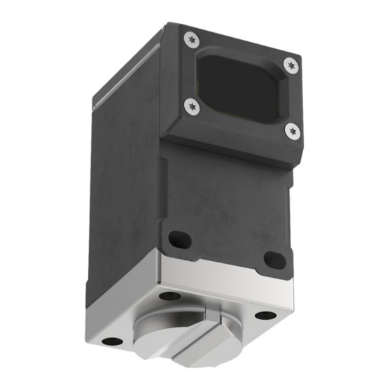
Always mount Q45VA / VAC so that the x-axis (reference label on side of sensor) is parallel to the main centerline of the asset. The
front of the Q45VA / VAC can face either direction as long as x-axis is parallel. Verify the z-axis is perpendicular (reference label on
side of sensor) with the radius of the of the asset main shaft.
Figure 1. Mounting orientation
x-axis
vibration sensitivity
There are four recommended ways to mount the Q45VA / VAC to the monitored asset:
•
Install the Q45VA Sensor Node Directly to the Asset
•
Install the Q45VA Sensor Node Using Bracket Assembly BWA-Q45VA-FESS
•
Install the Q45VA Sensor Node Using Magnetic Mount Bracket BWA-Q45VA-CMSS
•
Install the Q45 Using the Disc from BWA-Q45VA-FESS and Magnetic Mount Bracket BWA-Q45VA-CMSS
Install the Q45VA Sensor Node Directly to the Asset
Follow these instructions to mount the Q45VA Sensor Node directly to the asset you are monitoring. It is important to note that using
this method to mount the sensor may not allow future replacement without damaging the sensor.
1. Clean the bottom surface of the Q45VA Sensor Node.
2. Apply Loctite 330 and 7387 Activator (or similar adhesive) to the base of the Q45 housing.
3. Place the Q45VA on the asset, ensuring the correct alignment as shown in
4. After the Q45VA Sensor Node is aligned, hold for several minutes until the epoxy hardens.
Install the Q45VA Sensor Node Using Bracket Assembly BWA-Q45VA-FESS
Follow these instructions to mount the Q45VA Sensor Node to the monitored asset using the BWA-Q45VA-FESS bracket assembly.
The BWA-Q45VA-FESS bracket assembly includes:
•
Screw retainers (2)
•
Base plate (1)
Original Document
208986 Rev. E
®
radios. Do not discard these instructions.
Figure 2. Side view of monitored asset
X
Front
z-axis
vibration
sensitivity
Figure 4. Apply adhesive to the bottom of the Q45
29 March 2022
on page 1
on page 1
Apply adhesive to this
cleaned surface.
Before You Begin
Figure 3. Front view of monitored asset
Z
on page 3
on page 5
on page 1.
208986
Advertisement
Table of Contents

Summary of Contents for bannerman Q45VA
- Page 1 Network Manual (p/n 132607). Always mount Q45VA / VAC so that the x-axis (reference label on side of sensor) is parallel to the main centerline of the asset. The front of the Q45VA / VAC can face either direction as long as x-axis is parallel. Verify the z-axis is perpendicular (reference label on side of sensor) with the radius of the of the asset main shaft.
- Page 2 Screw Retainers 3. Position the base plate on the bottom of the Q45VA / VAC so that the four counterbores face up and the alignment mark faces the front of the Q45VA / VAC. Align the counterbores with the holes at the bottom of the device. See...
- Page 3 7. Using a felt marker, place a mark on the disc that aligns with the machined groove on the base plate. This marks the proper alignment of the Q45VA Sensor Node on your asset and aids in proper alignment if the Q45VA Sensor Node needs to be replaced in the future.
- Page 4 Screw Retainers 3. Position the base plate on the bottom of the Q45VA so that the four counterbore holes face up with v-groove of the magnet facing the front of the Q45VA. Align the counterbored holes with the holes at the bottom of the Q45VA.
- Page 5 Mounting the Q45VA / VAC using these combined parts offers another mounting solution, especially if you are mounting to aluminum or any other non-magnetic surfaces. Follow these instructions to mount the Q45VA / VAC to the monitored asset using the disc from the BWA-Q45VA-FESS bracket kit and the BWA-Q45VA-CMSS bracket.
Need help?
Do you have a question about the Q45VA and is the answer not in the manual?
Questions and answers