
Related Manuals for Studio Technologies IFB Plus Series


Summary of Contents for Studio Technologies IFB Plus Series
- Page 1 User Guide Issue 2, March 2015 This User Guide is applicable for serial numbers M2A-03451 and later Copyright © 2015 by Studio Technologies, Inc., all rights reserved www.studio-tech.com 50142-0315, Issue 2...
- Page 2 This page intentionally left blank.
-
Page 3: Table Of Contents
Operation ..............24 Configuration ..............29 Technical Notes ............31 Specifications ............... 33 Appendix A–IFB Plus Series Mechanical Drawings ..37 Appendix B–IFB Plus Series Optional Accessories ..42 Model 2A User Guide Issue 2, March 2015 Studio Technologies, Inc. -
Page 4: Revision History
1. Documented revised telco interface new capabilities and connection details: - Added the ability to connect both sources using jack 1. - Also added switched output connections. Issue 1, October 2013: 1. Initial release. Issue 2, March 2015 Model 2A User Guide Page 4 Studio Technologies, Inc. -
Page 5: Introduction
Introduction contains everything required to implement a full-featured system in a single space The IFB Plus Series Model 2A Central Con- (1U) of a 19-inch rack enclosure. The unit’s troller from Studio Technologies is a highly resources include multiple program inputs,... - Page 6 “all call” either or both IFB channels. This allows function. The Studio Technologies’ Model IFB signals intended for support person- 11A Gooseneck Microphone or a line-level nel and on-air talent to be simultaneously audio source can be connected.
- Page 7 Model 32A or Model 33A units can be con- by adding two resistors to the Model 2A’s nected to the talent amplifier output. For circuit board. application flexibility, the talent amplifier Model 2A User Guide Issue 2, March 2015 Studio Technologies, Inc. Page 7...
- Page 8 DC-biased (normally –48 volts) circuit LED. Also inactive in the standard audio provided by a local telephone company, long-distance carrier, or private telephone Issue 2, March 2015 Model 2A User Guide Page 8 Studio Technologies, Inc.
- Page 9 Internal Interrupt Microphone Contained behind the Model 2A’s front panel is an internal interrupt microphone. Associated with the microphone are two Figure 2. Model 22 Access Station Front View Model 2A User Guide Issue 2, March 2015 Studio Technologies, Inc. Page 9...
- Page 10 A allows a Model 22 and a Model 11A Goose- switch is used to select the interrupt audio neck Microphone to be mounted in a panel Issue 2, March 2015 Model 2A User Guide Page 10 Studio Technologies, Inc.
- Page 11 Model 2A Cen- tral Controller. On each talent amplifier the Figure 6. Model 32A Talent Amplifier (top) and Model 33A Talent Amplifier (bottom) Model 2A User Guide Issue 2, March 2015 Studio Technologies, Inc. Page 11...
-
Page 12: Installation
Issue 2, March 2015 Model 2A User Guide Page 12 Studio Technologies, Inc. - Page 13 2 to positive, and pins 1 and 3 to shield. Connections to the program audio inputs are made by way of the four 3-pin female Model 2A User Guide Issue 2, March 2015 Studio Technologies, Inc. Page 13...
- Page 14 Let the Model 2A become a useful note that each Model 32A and Model 33A part of your facility’s “bag of tricks!” Talent Amplifier has both a female and a Issue 2, March 2015 Model 2A User Guide Page 14 Studio Technologies, Inc.
- Page 15 • Auto disconnect upon telco-provided cellular telephone which in many cases is break in loop current (telephone line simply a standard audio signal. mode) Model 2A User Guide Issue 2, March 2015 Studio Technologies, Inc. Page 15...
- Page 16 Model 2A’s telephone interfaces, via to the interface 1 input whenever the Mod- a modular plug and cable, using shielded el 2A’s interface 1 circuitry is not active Issue 2, March 2015 Model 2A User Guide Page 16 Studio Technologies, Inc.
- Page 17 Refer to telephone interface 2 may be helpful. Figure 7 for details. Figure 7. Telco jack connection details Model 2A User Guide Issue 2, March 2015 Studio Technologies, Inc. Page 17...
- Page 18 1 connected to pin 1, pin 2 to pin 2, etc. the Model 22, allows connection of either a Shielded cable is required as the two audio Studio Technologies’ Model 11A Gooseneck buses linking the Model 22 units to a Model Microphone or a line-level audio signal.
- Page 19 Cable carry signal. runs longer than 500 feet are possible but should be carefully checked for correct The Studio Technologies’ Model 11A operation. Gooseneck Microphone is an unbalanced electret type, requiring an external source It’s come to the factory’s attention that...
- Page 20 Model 22’s terminal strip. One end of 5-position terminal strip to be active. In the black-colored wire is attached at the most cases a Studio Technologies’ Model factory to the ring lead of the jack. The oth- 11A gooseneck microphone has been con- er end should be attached to the –...
- Page 21 Figure 9 displays power source is not required. A 5-position the signals associated with the access screw terminal strip allows connection of station connector. an optional Studio Technologies’ Model 11A Gooseneck Microphone or a line-level Pin # Function signal. Common/Shield The Model 24 can be mounted using Interrupt Audio (–10 dBu nomimal)
- Page 22 The Gooseneck Microphone, available as an other end should be connected to the option from Studio Technologies, will SHLD terminal on the Model 24’s micro- be used with a Model 24. Setting the phone input.
- Page 23 The Model 2A operates directly from AC mains power of 100 to 240 volts, 50/60 hertz, 24 watts maximum. As a “universal mains input” device, there are no switches Model 2A User Guide Issue 2, March 2015 Studio Technologies, Inc. Page 23...
-
Page 24: Operation
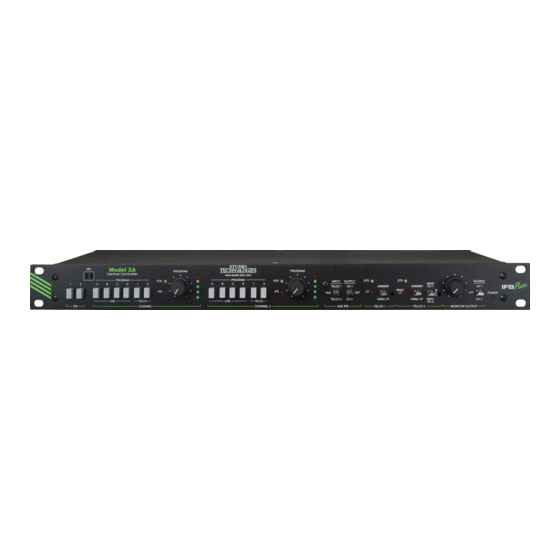
IFB 1 and interrupt condition is caused by the VOX 2. Pressing either switch mutes program function. Figure 10. Detail of Model 2A Central Controller Front Panel Issue 2, March 2015 Model 2A User Guide Page 24 Studio Technologies, Inc. - Page 25 The red LED, labeled LC for loop automatically interrupt the program signal. current, lights any time the interface is By contrast, using the Model 2A’s internal Model 2A User Guide Issue 2, March 2015 Studio Technologies, Inc. Page 25...
- Page 26 “hot” signal can be on the telephone line. It will light continu- attenuated. The trim pot is accessible via a ously any time the interface is set for the Issue 2, March 2015 Model 2A User Guide Page 26 Studio Technologies, Inc.
- Page 27 To prevent possible Stations have been connected, their push- acoustical feedback the monitor output button switches should be dimly lit. will mute. Using the meters, observe that Model 2A User Guide Issue 2, March 2015 Studio Technologies, Inc. Page 27...
- Page 28 Use the VOX output switch to assign the the end of the selected number of “rings. VOX output to one of the IFB channels. On Issue 2, March 2015 Model 2A User Guide Page 28 Studio Technologies, Inc.
-
Page 29: Configuration
If it falls below a threshold the output DC be adjusted so as to roughly match each Model 2A User Guide Issue 2, March 2015 Studio Technologies, Inc. Page 29... - Page 30 –10 dBu as shown on the meter. Issue 2, March 2015 Model 2A User Guide Page 30 Studio Technologies, Inc.
-
Page 31: Technical Notes
Definition of Level able auto answer. The DIP switch, located Studio Technologies has opted to use the on the Model 2A’s printed circuit board, dBu designation as it seems to be quite ra- is labeled SW3. - Page 32 By replacing this resistor with a “0 ohm” resistor or jumper strap, full at- tenuation can be achieved. Contact the factory for details. Issue 2, March 2015 Model 2A User Guide Page 32 Studio Technologies, Inc.
-
Page 33: Specifications
Type: electronically balanced, capacitor coupled, channel 1 or 2 audio intended to drive 2000 ohm or greater loads Send Audio Level: –6 dBu, nominal Level: +4 dBu, nominal, +25 dBu maximum Model 2A User Guide Issue 2, March 2015 Studio Technologies, Inc. Page 33... - Page 34 Microphone Input: Application: designed to drive loads of 8 ohms or Compatibility: 2-wire electret, designed for use greater with Studio Technologies’ Model 11A Gooseneck Microphone (purchased separately) Access Station Interface: allows connection of up Intended Input Level: –25 dBu nominal to four Model 22 or Model 24 Access Stations Microphone Power: +5 volts DC, current limited.
- Page 35 Microphone Input: Application: intended for use with one Model 24 Compatibility: 2-wire electret, designed for use Access Station and one Model 11A Gooseneck with Studio Technologies’ Model 11A Gooseneck Microphone Microphone (purchased separately) Dimensions (with Model 24 attached): Intended Input Level: –25 dBu nominal 19.0 inches wide (48.3 cm)
- Page 36 Weight: 0.6 pounds (0.3 kg) Weight: 0.6 pounds (0.3 kg) Specifications and information contained in this User Guide subject to change without notice Issue 2, March 2015 Model 2A User Guide Page 36 Studio Technologies, Inc.
-
Page 37: Appendix A-Ifb Plus Series Mechanical Drawings
Appendix A–IFB Plus Series Mechanical Drawings Model 2A User Guide Issue 2, March 2015 Studio Technologies, Inc. Page 37... - Page 38 Issue 2, March 2015 Model 2A User Guide Page 38 Studio Technologies, Inc.
- Page 39 Model 2A User Guide Issue 2, March 2015 Studio Technologies, Inc. Page 39...
- Page 40 Issue 2, March 2015 Model 2A User Guide Page 40 Studio Technologies, Inc.
- Page 41 Model 2A User Guide Issue 2, March 2015 Studio Technologies, Inc. Page 41...
-
Page 42: Appendix B-Ifb Plus Series Optional Accessories
Appendix B–IFB Plus Series Optional Accessories Model 11A Gooseneck Microphone (Order Code: M11A) (For use with Model 22 and Model 24 Access Stations, Model 25A and Model 27A 19-Inch Rack Adapters, and Model 28A Panel Adapter) Model 25A 19-Inch Rack Adapter (Order Code: M25A)
Need help?
Do you have a question about the IFB Plus Series and is the answer not in the manual?
Questions and answers