
Subscribe to Our Youtube Channel
Summary of Contents for SIEB & MEYER Drive System SD2x
- Page 1 SIEB & MEYER Drive System SD2x Operating Terminal 0362150 and 0362153 Operating terminal to control a drive of the series SD2S, SD2M, SD2B or SD2B plus D-00000021.3 2022-06-09...
- Page 2 SIEB & MEYER Asia Co. Ltd. 5 Fl, No. 578, Sec. 1 Min-Sheng N. Road Kwei-Shan Hsiang Guishan Dist., Taoyuan City 33393 Taiwan Phone: +886 3 311 5560 Fax: +886 3 322 1224 info@sieb-meyer.tw Drive System SD2x - Operating Terminal 0362150 and 0362153...
-
Page 3: Table Of Contents
Actual Value Display of Devices without USB Support..............26 14.2.2 Display........................28 14.2.3 Controlling the Drive..................... 14.3 PROGRAM MENU....................... 14.3.1 Enter password......................30 14.3.2 PARAMETER MENU....................30 14.3.2.1 Change parameters........................14.3.3 SAVE PARAMETER..................... 14.3.4 SELECT PARAMSET....................14.3.5 READ PARAMETER....................Drive System SD2x - Operating Terminal 0362150 and 0362153... - Page 4 CLEAR TERMINAL DATA.................... 14.3.8 CHANGE PASSWORD....................14.4 INFO MODE......................... 14.5 AXIS RESET........................ 14.6 TRANSPARENT MODE....................37 14.6.1 TRANSPARENT MODE for USB..................38 14.6.2 TRANSPARENT MODE for RS232................14.7 RESET..........................38 14.8 BRIGHTNESS......................Status Messages..............Index..................41 Drive System SD2x - Operating Terminal 0362150 and 0362153...
-
Page 5: About This Manual
Indicates a hazardous situation which, if not avoided, may result in property damage. → Follow the instructions in this manual to avoid danger. Technical Symbols Symbol Description LED indicator: LED on LED indicator: LED off LED indicator: LED flashes Drive System SD2x - Operating Terminal 0362150 and 0362153... -
Page 6: General Information
Read the hardware documentation of the connected drive and PC and pay attention to the safety instructions. This manual provides information on: ▶ views, dimensional drawings, connections ▶ pin assignments, mounting ▶ software configuration ▶ functions ▶ status messages Drive System SD2x - Operating Terminal 0362150 and 0362153... -
Page 7: Operating Terminal Versions
6/7), X62 (COM1), X63 (JTAG download socket) and switch S1 (see chapter 10 “Hardware Configuration”, page 19) and X60-1 (download socket: USB, type B) – software version: V4.xx – used for serial number 1000387005 and higher Drive System SD2x - Operating Terminal 0362150 and 0362153... -
Page 8: Operating Terminal 0362150
Operating Terminal 0362150 Operating Terminal 0362150 Fig. 1: Operating terminal 0362150 (for plug-on mounting to the drive) Dimensions 0362150 Fig. 2: Dimensions of the operating terminal 0362150 in mm (inch) Drive System SD2x - Operating Terminal 0362150 and 0362153... -
Page 9: Operating Terminal 0362153
Operating Terminal 0362153 Operating Terminal 0362153 Fig. 3: Operating terminal 0362153 (for switch cabinet installation) Dimensions 0362153 Fig. 4: Dimensions of the operating terminal 0362153 in mm (inch) Drive System SD2x - Operating Terminal 0362150 and 0362153... -
Page 10: Connectors
Fig. 5: PCB 036210043 (example illustration of operating terminal 0362150) Connector Meaning Pin assignment USB port to the PC page 13 Serial interface COM2 (RS232) to the PC page 13 Serial interface COM1 (RS232) to the drive page 15 Drive System SD2x - Operating Terminal 0362150 and 0362153... -
Page 11: Connectors On Pcb 036210043.1/036210043.2
Serial interface COM2 (RS232 and CAN bus) to the PC page 14 Serial interface COM1 (RS232) to the drive page 15 JTAG download socket to load new software into the operating page 15 terminal Drive System SD2x - Operating Terminal 0362150 and 0362153... -
Page 12: Connectors On Pcb 036210043.4
Serial interface COM1 (RS232) to the drive page 15 JTAG download socket to load new software into the operating page 15 terminal Slide switch to set the hardware configuration page 19 Drive System SD2x - Operating Terminal 0362150 and 0362153... -
Page 13: Connector Pin Assignment
The USB download socket is a 6-pole row of holes and is used by the SIEB & MEYER service staff to load a new operating terminal software. If you want to load a new soft- ware into the operating terminal, please contact the SIEB & MEYER service. Drive System SD2x - Operating Terminal 0362150 and 0362153... -
Page 14: X60-1 - Usb-B Download Socket
PCB version 036210043.3 and higher: The pins 2 and 3 allow connecting straight-through (1:1) as well as cross-over cables. The switch S1 defines the internal forwarding of the data (see chapter 10 “Hardware Configuration”, page 19). Stud bolt flange: max. tightening torque = 0.7 Nm Drive System SD2x - Operating Terminal 0362150 and 0362153... -
Page 15: X62 - Com1 Interface
The JTAG download socket is an 8-pole row of holes and is used by the SIEB & MEYER service staff to load a new operating terminal software. If you want to load a new soft- ware into the operating terminal, please contact the SIEB & MEYER service. Drive System SD2x - Operating Terminal 0362150 and 0362153... -
Page 16: Connection To The Drive
The female connector X62 (COM1) of the operating terminal 0362153 is connect- ed to the male COM1 connector of the drive by means of an extension cable. For the mounting instructions and a mounting template, refer to the technical information “TIE_OperatingTerminal_0362153_Mounting.pdf”. Drive System SD2x - Operating Terminal 0362150 and 0362153... -
Page 17: Switch Cabinet Installation
SIEB & MEYER recommends a separate voltage supply for this purpose. If a larger dis- tance must be covered, you can connect a separate voltage source to the operating ter- minal. Drive System SD2x - Operating Terminal 0362150 and 0362153... - Page 18 Property damage when using a separate voltage supply → When using a separate voltage source the voltage supply from the drive must be disconnected. Otherwise overvoltages can cause damage at the operating termi- nal. Drive System SD2x - Operating Terminal 0362150 and 0362153...
-
Page 19: Hardware Configuration
Cable S1 switch position Internal forwarding cross-over Pin 2 and pin 7 Pin 3 and pin 6 straight-through (1:1) Pin 2 and pin 6 Pin 3 and pin 7 Drive System SD2x - Operating Terminal 0362150 and 0362153... -
Page 20: Software Configuration
Note The operating terminal cannot control the drive if another control channel (and setpoint channel up to version 3.08) have been selected or if the drive-setup-tool is active. Drive System SD2x - Operating Terminal 0362150 and 0362153... - Page 21 Software Configuration Digital input D-IN0: No function On the “Parameter” tab, open the “Digital inputs” page. For the D-IN0 input, select “No function” from the drop-down list. Drive System SD2x - Operating Terminal 0362150 and 0362153...
-
Page 22: Switching On The Operating Terminal
USB TRANSPARENT MODE ▶ RS232 TRANSPARENT MODE ▶ TERMINAL RESET ▶ BRIGHTNESS The MAIN MENU is superordinated. Note The two transparent modes are only used by terminals with USB and RS232 support. Drive System SD2x - Operating Terminal 0362150 and 0362153... -
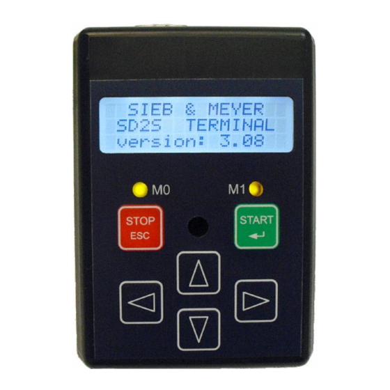
Page 23: Operating Elements
The two yellow illuminated LEDs indicate the states of the operating terminal and drive. In addition, they indicate in some of the menu items, which of the both keys ESC (M0) and ENTER (M1) can be pressed. Drive System SD2x - Operating Terminal 0362150 and 0362153... -
Page 24: Display
All displayed values are read from the drive as objects. Each value has an object num- ber assigned. Via these object numbers, you can access the related object in the Object browser of the drivemaster2 user interface. Drive System SD2x - Operating Terminal 0362150 and 0362153... -
Page 25: Functions Of The Terminal
“HSBLOCK”, the current is displayed as sine wave peak amplitude (A), for “HSPWM”, “HSPAM” und “U/f” as RMS value (Arms). (The DeviceDriveFunctionMode “HSPWM” is supported for software version (operating terminal) 3.11 and higher and “U/ f” for version 3.12 and higher.) Examples Drive System SD2x - Operating Terminal 0362150 and 0362153... -
Page 26: Actual Value Display Of Devices Without Usb Support
If the drive status is “Operation enabled”, a progress bar for the load (object 324 for Odict version 8 and higher) on the parameterized rated motor current is displayed in %. Drive System SD2x - Operating Terminal 0362150 and 0362153... - Page 27 V/f control, the active current (object 430) is displayed instead of the reference cur- rent. In addition, the actual apparent current (object 431) and the actual motor voltage (object 434) are displayed for this drive function. Drive System SD2x - Operating Terminal 0362150 and 0362153...
-
Page 28: Led Display
– Up to software version (operating terminal) 3.08: Serial interface / RS485 / USB – Software version (operating terminal) 3.09 and higher: The selected setpoint channel must support the used parameters. Drive System SD2x - Operating Terminal 0362150 and 0362153... -
Page 29: Program Menu
Via the “Cursor up” and “Cursor down” keys, you can select the different menu items. When you press the ENTER key, the display will switch to the selected menu. When you press the ESC key, the display will return to the MAIN MENU. Drive System SD2x - Operating Terminal 0362150 and 0362153... -
Page 30: Enter Password
If the parameter input via terminal is deactivated, the er- ror message “function not allowed” will be displayed for one second and the display will switch back to PROGRAM MENU. Drive System SD2x - Operating Terminal 0362150 and 0362153... -
Page 31: Change Parameters
You must confirm each value by pressing ENTER. The next value will then be automatically displayed. Via the ESC key, you can abort the input. All already confirmed values will be applied. Drive System SD2x - Operating Terminal 0362150 and 0362153... -
Page 32: Save Parameter
If changing the parameter set is allowed, you must enter the correct password before you can select the desired parameter set. Drive System SD2x - Operating Terminal 0362150 and 0362153... -
Page 33: Read Parameter
If there is an error during reading, the process will be canceled and the following error message will be displayed: If there are no parameters stored in the drive, the following error message will appear: Drive System SD2x - Operating Terminal 0362150 and 0362153... -
Page 34: Write Parameter
If thera are no parameters stored in the operating terminal or the drive is in BIOS mode, the parameters cannot be written to the drive. The following message will ap- pear: Drive System SD2x - Operating Terminal 0362150 and 0362153... -
Page 35: Clear Terminal Data
Afterwards, the display switches back to the PROGRAM MENU. Drive System SD2x - Operating Terminal 0362150 and 0362153... -
Page 36: Change Password
▶ drive type (object 117) ▶ Name of parameter set (object 22) ▶ motor name (object 44) ▶ serial number (object 7) ▶ Operation time meter since last booting (object 9) Drive System SD2x - Operating Terminal 0362150 and 0362153... -
Page 37: Axis Reset
The two transparent modes are only used by terminals with USB and RS232 support. In the TRANSPARENT MODE, there are two modes: ▶ TRANSPARENT MODE for USB ▶ TRANSPARENT MODE for RS232 Drive System SD2x - Operating Terminal 0362150 and 0362153... -
Page 38: Transparent Mode For Usb
Up to PCB version 036210043.2, up to software version (operating terminal) 3.xx A reset (warm boot) allows to restart the operating terminal application in the AU- TOMATIC MODE and in the TRANSPARENT MODE. A possible bridge at COM2 is left unconsidered. Drive System SD2x - Operating Terminal 0362150 and 0362153... -
Page 39: Brightness
When quitting the menu item, the value for the brightness is saved in the Flash EPROM. During initialization and when the operating terminal data are cleared, the saved value is read from the Flash EPROM. Drive System SD2x - Operating Terminal 0362150 and 0362153... -
Page 40: Status Messages
▶ The logic software or the firmware does not support features that are required by the parameter set, e.g. the parameterized bus system is not supported. Drive System SD2x - Operating Terminal 0362150 and 0362153... -
Page 41: Index
X59 – COM2 drivemaster2 configuration X60 – USB (service interface) X60-1 – USB-B (service interface) X61 – COM2 X62 – COM1 Errors X63 – JTAG (service interface) Keys LEDs Main menu Drive System SD2x - Operating Terminal 0362150 and 0362153...
Need help?
Do you have a question about the Drive System SD2x and is the answer not in the manual?
Questions and answers