
Related Manuals for Heyuan Intelligence ASDU-LS

Summary of Contents for Heyuan Intelligence ASDU-LS
- Page 1 ASDU-LS Intelligent Gateway User Manual (V1.1) Heyuan Intelligence Technology Co., Ltd...
- Page 2 IMPORTANT DECLARATIONS Copyright © 2018 Heyuan Intelligence Technology Co., Ltd All Rights Reserved This manual may not be reproduced, copied, transmitted or transcribed in whole or in part by any means without the expressed written permission of Heyuan. Any shall be investigated for legal responsibility in violation of copyright or other intellectual property rights of the Company.
-
Page 3: Table Of Contents
Contents Chapter 1 Product Overview ……………………………………………………………………………...1 Chapter 2 Functional Overview …………………………………………………………………………..1 Chapter 3 Technical Parameters …………………………………………………………………………1 Chapter 4 Hardware Instruction ………………………………………………………………………….2 Chapter 5 Dimension & Installation ……………………………………………………………………..4 Chapter 6 Key Performance Indicator …………………………………………………………………..5 Chapter 7 Running Configuration Requirement ………………………………………………………5 Chapter 8 First Time to Configure……………………………………………………………………….6 Chapter 9 Database Setting ………………………………………………………………………………7 Chapter 10 Device Management ………………………………………………………………………23 Chapter 11 Real-time Monitor ………………………………………………………………………….26... -
Page 4: Chapter 1 Product Overview
ASDU-LS Intelligent Gateway can also be used as the general control sub-station and the front-end processor of the integrated automation system to form the middle layer of the automatic system. It... -
Page 5: Chapter 4 Hardware Instruction
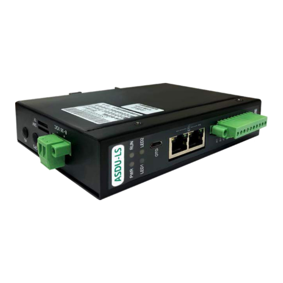
3.2 Interfaces & Extension Ethernet: 2* independent Ethernet ports, 10/100Mbps USB: 1*USB OTG Serial Ports: 4* isolated RS485 CAN: 1*isolated CAN2.0 Extension: 1*Mini-PCIe (2G/3G/GPRS/4G optional) 3.3 Power Supply Power Supply: DC8~36V Power Consumption: <15W 3.4 Software Configuration Linux 4.1 Embedded various communication protocols: Modbus-RTU Protocol, Modbus-TCP/IP Protocol, DL/T-645 Protocol, IEC60870-102,103,104 Protocol, MQTT Protocol, HTTP Protocol etc. - Page 6 Indicator Lights Indicator lights of front power, running Indicator Light Functions Indicator Light Functions Red light, indicating LED2 Yellow light, reserved power Green light, Indicating receiving indicating running data Blue light, Indicating transmitting LED1 indicating 4G state data USB Interface 1*OTG for debugging ...
-
Page 7: Chapter 5 Dimension & Installation
Extensible TF card Power Supply Power Supply: DC8~36V "-" connected to the negative pole of power supply, "+" connected to the positive pole of power supply. Chapter 5 Dimension & Installation 5.1 Dimension A. Din-rail Mounting Dimension (Unit: mm) B. -
Page 8: Chapter 6 Key Performance Indicator
5.2.2 Power-on Inspection ASDU-LS Intelligent Gateway will start working once it is power on. The power indicator light “PWR” lights up and the run light “RUN” flashes regularly, which shows power is correctly on and ASDU-LS is working normally. Chapter 6 Key Performance Indicator 6.1 Capacity for ASDU-LS Intelligent Gateway... -
Page 9: Chapter 8 First Time To Configure
Sqlite3 Chapter 8 First Time to Configure After the gateway is powered on, the Ethernet interfaces of the gateway ASDU-LS can be access to IP address automatically. Press the reset button and the Ethernet interfaces will be enabled. The IP addesses will be changed to default IP addresses 192.168.137.1 and 192.168.138.1 automatically. -
Page 10: Chapter 9 Database Setting
Screen 8-2 Local Communication Parameter Configuration Chapter 9 Database Setting 9.1 Software Function Interface Menu Bar Tool Bar Navigation Bar Editing Area Screen 9-1 Configuration Software ① Menu Bar: including “Device Management”, “Set Database”, “Real-time Monitor” and “About”, which respectively refer to the system setting interfaces, real-time data monitoring interfaces and copyright information of the gateway. - Page 11 9.2 Configuration Flow Chart The functions of remote configuration management, real-time monitoring, communication message monitoring and remote protocol debugging etc. will be implemented with the upper-computer configuration software. Screen 8-2 Configuration Flow Chart (recommended) 9.3 Parameter Template Configuration 9.3.1 Terminal Model Sheet Configuration In the navigation bar, choose “Terminal Model Sheet”.
- Page 12 Screen 9-4 Terminal Telemetry Register Table Configuration ① Terminal Coefficient: referring to the multiplier relation, that is real-time data= readout data x terminal coefficient. ② Telemetry Scale: referring to the divisor relation, that is real-time data= readout data / terminal scale.
- Page 13 ② Energy Scale: referring to the divisor relation, that is real-time data= readout data / terminal scale. 9.3.4 Terminal Digital Signal Register Table Configuration Click buttons 【+/—】 in the tool bar to add or delete terminal energy registers and edit the details. Screen 9-6 Terminal Digital Signal Register Table Configuration Digital Signal Type: Single-Point Digital Signal, Double-Point Digital Signal 9.3.5 Terminal Setting Value Register Table Configuration...
- Page 14 Screen 9-8 Terminal Telecontrol Register Table Configuration Configure the telecontrol registers of the template terminals. 9.4 Gateway Configuration 9.4.1 Communication Protocol Sheet Configuration The software supports protocol configurations of 101 acquisition and forwarding protocol, 103 acquisition protocol, 104 acquisition and forwarding protocol, Modbus acquisition and forwarding protocol, 1997/2007 DL/645 protocol and CJ/T188 protocol etc.
- Page 15 (a) Modbus-RTU Acquisition Protocol Configuration a.1 General Parameter Configuration Editing Screen 9-10 Modbus-RTU Acquisition Protocol General Parameter a.2 Edit Inquiry Frame Screen 9-11 MODBUS-RTU Acquisition Protocol Inquiry Frame Editing The “Edit Inquiry Frame” interface is used to configure the telemetry data, energy data and digital signal data, and edit terminal model, function code, register address and quantity etc.
- Page 16 Screen 9-12 Telemetery Details Editing of MODBUS-RTU Acquisition Protocol Inquiry Frame Edit telemetery names, register address, data type and endianness etc. Screen 9-13 Energy Details Editing of MODBUS-RTU Acquisition Protocol Inquiry Frame Edit energy names, register address, data type and endianness etc. a.3 Edit Control Frame Screen 9-14 MODBUS-RTU Acquisition Protocol Telecontrol Frame Editing Edit telecontrol type, function code, register address and endianness etc.
- Page 17 Screen 9-15 Details Editing of MODBUS-RTU Acquisition Protocol Telecontrol Frame b) MODBUS-RTU Forwarding Protocol Configuration Screen 9-16 MODBUS-RTU Forwarding Protocol Configuration c) 1997 DL/645 Protocol Configuration...
- Page 18 Screen 9-17 Dictionary Editing of 1997 DL/645 Protocol Configuration Formats of commands sent of 1997 DL/T645 protocol is as follows. Send original message: 68 03 00 00 00 00 00 68 01 02 44 E9 03 16 Message after Decreasing 33H: 68 03 00 00 00 00 00 68 01 02 11 B6 03 16 Address: 030000000000H Control Code: C = 01H Identification Code: DI1DI0 = B611H...
- Page 19 Screen 9-19 Dictionary Editing of 2007 DL/645 Protocol Configuration Formats of commands sent of 2007 DL/T645 protocol is as follows. Send original message:68 61 01 00 00 00 00 68 11 04 33 34 34 35 17 16 Message after Decreasing 33H: 68 61 01 00 00 00 00 68 11 04 00 01 01 02 17 16 Address: A0-A5 = 610100000000H Control Code: C = 11H Identification Code: DI3DI2DI1DI0 = 02010100H...
- Page 20 Screen 9-20 2007 DL/645 Protocol Configuration e) 101 Acquisition Protocol Configuration Screen 9-21 101 Acquisition Protocol Configuration f) 101 Forwarding Protocol Configuration Screen 9-22 101 Forwarding Protocol Configuration...
- Page 21 g) 103 Acquisition Protocol Configuration Screen 9-23 103 Acquisition Protocol Configuration h) 104 Acquisition Protocol Configuration Screen 9-24 104 Acquisition Protocol Configuration i) 104 Forwarding Protocol Configuration...
- Page 22 Screen 9-25 104 Forwarding Protocol Configuration j) CJ/T188 (Water Meter) Protocol Configuration Screen 9-26 CJ/T188 (Water Meter) Protocol Configuration...
- Page 23 Screen 9-27 CJ/T188 (Water Meter) Protocol Details Configuration 9.4.2Communication Channel Configuration Screen 9-28 Communication Interface Details Configuration Configure the information of serial ports 9.4.3Communication Terminal Configuration...
- Page 24 Screen 9-29 Communication Terminal Configuration Configure the information of connected terminals. 9.4.4Front-end Communication Sheet The sheets of front-end communication telemetry, energy, digital signal, setting value, telecontrol will be automatically generated based on the configuration above. Screen 9-30 Font-end Communication Sheet Configuration...
- Page 25 9.5 Forwarding Configuration 9.5.1Forwarding Protocol Configuration Please refer to the 7.4.2 communication protocol configuration 9.5.2Forwarding Channel Configuration Screen 9-31 Forwarding Channel Configuration 9.5.3 Forwarding Terminal Configuration In the communication terminal sheet, the communication interface is the configured forwarding interface. Screen 9-32 Forwarding Terminal Configuration 9.5.4Forwarding Information Sheet Configuration...
-
Page 26: Chapter 10 Device Management
Screen 9-33 Forwarding Information Sheet Configuration Chapter 10 Device Management 10.1 Communication Configuration 10.1.1 Local Communication Parameter Configuration The local communication parameter configuration is used for debugging when the gateway is directly connected to the computer. (Please refer to the chapter 7 for details) Screen 10-1 Device Management... - Page 27 10.1.2 Cloud Communication Parameter Configuration It is used for the gateway ASDU-LS equipped with 4G function. On interface “Device Management”, choose “Cloud Communication Parameter Configuration ” and fill cloud service IP address and gateway details. Screen 10-2 Cloud Communication Parameter Configuration 10.2 Service Configuration...
- Page 28 10.3 Program Upgrading Screen 10-4 Program Upgrading Choose file type from “Database File”, “Configuration File”, “Network Configuration” and “Program Upgrading Package”. Please choose the corresponding file type and path and then click “send file”. 10.4 File Calling Screen 10-5 Calling File The “Database File”, ‘Configuration File”, “Configuration Message”, “Telemetry”, “Energy”...
-
Page 29: Chapter 11 Real-Time Monitor
Chapter 11 Real-time Monitor Screen 11-1 Real-time monitoring-Telemetry Information On “Real-time Monitor” interface, the real-time data received by parsing data messages of the gateway can be viewed. U can choose to read real-time energy, digital signal and communication message. Chapter 12 Application Instruction 12.1 System Solution ASDU003 ASDU004... -
Page 30: Chapter 13 After-Sales Service
Screen 12-2 Application Fields Chapter 13 After-sales Service Product Warranty 1. The product warranty period is one year. 2. The company is responsible for free maintenance or exchange within one-year warranty period. 3. The cost of the components and freight shall be charged for improper meter installation and/or operation.
Need help?
Do you have a question about the ASDU-LS and is the answer not in the manual?
Questions and answers