Advertisement
Quick Links
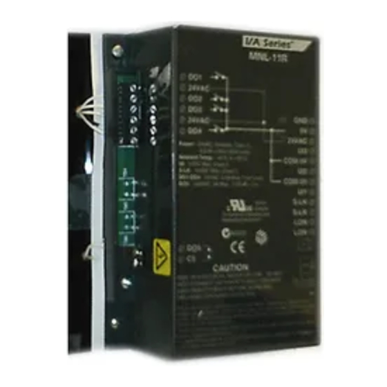
Application
The sLON-5 and sLON-6 Controllers are interoperable
controllers designed in accordance with L
guidelines. When programmed using WPT Software
Tool, these controllers provide control for fan coil and
unit ventilator applications. These controllers feature:
screw terminal blocks; three universal inputs,
software-configured to respond to one of five input
types; one (sLON-5) or three (sLON-6) high-voltage
relay output(s); four 24 Vac Triac (digital) outputs; and
an S-Link interface for connection to an optional
sLON-WTSx digital sensor.
The sLON-5 and sLON-6 controllers conform to the
L
M
Fan Coil Unit functional profile (8020)
ON
ARK
providing open communication and interoperability with
third party L
M
devices and greater freedom in
ON
ARK
system design. These controllers can function in
standalone mode or as part of a L
Free Topology network.
Model Chart
Model
Description
Fan Coil Controller
sLON-5
with One High
Voltage Relay
Fan Coil Controller
sLON-6
with Three High
Voltage Relays
INSTALLATION
Inspection
Solidyne Corporation - www.solidyne.com
®
M
ON
ARK
®
W
TP/FT-10
ON
ORKS
Inputs / Outputs
• 3 Universal Inputs
(software-configured)
• 4 DO Triacs, capable of
switching a total load of
0.5 A @ 24 Vac.
• 1 DO Relay Output,
250 Vac, 3 A.
• S-Link Support.
• 3 Universal Inputs
(software-configured)
• 4 DO Triacs, capable of
switching a total load of
0.5 A @ 24 Vac.
• 3 DO Relay Outputs,
250 Vac, 3 A.
• S-Link Support.
Inspect carton for damage. If
damaged, notify carrier
immediately. Inspect
controllers for damage upon
receipt.
firealarmresources.com
TECH/DATA SHEET
sLON-5
sLON-6
sLON VAV Controller
sLON-5
sLON-6
sLON-5, sLON-6 rev1 03/2005
Advertisement

Summary of Contents for Solidyne sLON-5
- Page 1 24 Vac Triac (digital) outputs; and an S-Link interface for connection to an optional sLON-WTSx digital sensor. The sLON-5 and sLON-6 controllers conform to the sLON-5 Fan Coil Unit functional profile (8020) providing open communication and interoperability with...
- Page 2 – 0 to 5 Vdc analog voltage transmitter – 4 to 20 mAdc analog current transmitter – Digital dry switched contact (switched contact resistance must be less than 300 ohms for closed contact and greater than 1.5K ohms for open contact) sLON-5, sLON-6 rev1 03/2005 firealarmresources.com...
- Page 3 Precautions General Warning: The sLON-5 and sLON-6 controllers are not suitable for exposed mounting on a wall or panel, or in any other easily accessible place due to the possibility of personal contact with the high-voltage terminals. They must be mounted inside a suitable grounded metal enclosure (Figure-2).
- Page 4 Location The sLON-5 and sLON-6 controllers are suitable for indoor use only (IP 20). See Figure-1 for mounting dimensions. When selecting a mounting location, make certain the following conditions are met: Warning: The sLON-5 and sLON-6 controllers are not suitable for exposed mounting on a wall or panel, or in any other easily accessible place due to the possibility of personal contact with the high-voltage terminals.
- Page 5 DIN Rail Controller (sLON-5 Shown) 1 This example illustrates the use of a suitable grounded metal enclosure to mount an sLON-5 or sLON-6 controller. Dedicated Ground This controller is not suitable for exposed mounting on a wall Wire from Enclosure...
- Page 6 Wiring The following electrical connections can be made to sLON-5 and sLON-6 controllers: Communications wiring, including: • • S-LK wiring between an sLON-5 and sLON-6 controller and an sLON-WTSx Sensor. • network (LON) connection, including connections to other sLON-type ORKS controllers.
-
Page 7: Communications Wiring
Communications Communications wiring includes wiring between the sLON-5 or sLON-6 controller and one sLON-WTSx Sensor, as well as wiring between the sLON-5 or sLON-6 controller and a Wiring Network (LON). ORKS S-Link and LON Wiring Precautions Caution: Communication wire pairs must be dedicated to S-Link and LON communications. They •... - Page 8 ORKS Figure-8 sLON-5 and sLON-6 L Network Terminal Connections. ORKS 4. If the sLON-5 or sLON-6 controller is to be connected to a L network, ORKS determine the topology chosen for the TP/FT-10 segment, then connect to additonal controllers. To allow the sLON-5 or sLON-6 to share data with other L...
- Page 9 Note: UI and S-Link wiring can share a single conduit. 10K Thermistor with 11K Shunt Resistor Any of the sLON-5 or sLON-6 controller’s UI inputs can be configured for Thermistor input. When configured in this way, a 10K ohm Thermistor with 11K ohm shunt resistor may be connected to the sLON-5 or sLON-6 controller to sense the space temperature.
- Page 10 Figure-9 Typical Wiring for 10K Thermistor with 11K Shunt Resistor. Resistive — 1K Balco or 1K Platinum Input Any of the sLON-5 or sLON-6 controller’s UI inputs can be configured for the 1K Balco or Platinum Element Resistive Sensor. Make the connections according to the diagram in Figure-10.
- Page 11 Analog Voltage Input Any of the sLON-5 or sLON-6 controller’s UI inputs can be configured for the 0 to 5 Vdc Analog Voltage Transmitter input. Make the connections according to the diagram in Figure-11. sLON-5 0 to 5 Vdc Power...
- Page 12 Digital Triac Outputs (DOs) The sLON-5 and sLON-6 controllers contain four 24 Vac (digital) Triac outputs. Before wiring these outputs, refer to Table-3 for their electrical specifications. Table-3 Triac Output Electrical Specifications. Characteristic Specification Maximum Triac Switched Output Voltage 24 Vac terminal voltage...
- Page 13 Connect the sLON-5 or sLON-6 controller’s high-voltage relay terminal(s) (DO5 and C5 for the sLON-5; DO5, C5, DO6, C6, DO7, and C7 for sLON-6) to 230 Vac power and the switched 230 Vac motor(s) as shown in Figure-15 and Figure-16.
-
Page 14: Power Supply Wiring
Power Supply Wiring Power Supply Wiring Precautions Caution: • The sLON-5 and sLON-6 controllers contain a non-isolated half-wave rectifier power supply and must not be powered by transformers used to power other devices containing non-isolated full-wave rectifier power supplies. •... - Page 15 To rest of the sLON-5 network ORKS Class 2 wiring. sLON-6 Figure-18 Power Supply Connection — Multiple Controllers Powered from a Separate Class 2 Power Source and Sharing Communications in a Free Topology Segment. sLON-5, sLON-6 rev1 03/2005 firealarmresources.com...
-
Page 16: Lon Works Network
Installation on a In addition to functioning in standalone mode, the sLON-5 or sLON-6 controller may be connected to a L network for data sharing with other L devices. This is ORKS ORKS Network ORKS made possible by addressing the controller on the network and performing the desired network bindings. - Page 17 6.Make certain that the current requirements of the controlled device do not exceed the rating of the controller’s digital outputs. Communications Hardware Checkout In addition to functioning in standalone mode, the sLON-5 or sLON-6 controller may be connected to a L network for data sharing with other L devices.
- Page 18 Power and Data Transmission LED (Green) Data Reception LED (Amber) ORKS Network Jack Service LED (Red) Service Pin Figure-19 Location of Controller LEDs. sLON-5, sLON-6 rev1 03/2005 firealarmresources.com...
- Page 19 Off usually indicates a normal state. In this state, the If the controller is able to accept Anytime controller operates normally, and you can download and/or run a downloaded HVAC and/or run HVAC applications. application, no action is required. sLON-5, sLON-6 rev1 03/2005 firealarmresources.com...
- Page 20 Service Components within the sLON-5 and sLON-6 controllers cannot be field repaired. If there is a problem with the controller, follow the steps outlined in the “Checkout“ section. If the problem persists, record the following hardware setup information before contacting Solidyne Technical Support: Version number of the application software.
Need help?
Do you have a question about the sLON-5 and is the answer not in the manual?
Questions and answers