
Summary of Contents for KOHJINSHA VERSA Beam
- Page 1 VERSA Beam Antenna Controller INSTRUCTION MANUAL Please keep this manual after you read for maintenance purpose Rev3.01 Jun. 2020 - 0 -...
-
Page 2: Table Of Contents
6-7. What You Should Keep in Mind When You Measure SWR ------- ------ --22 6-8. Frequency Segment Width Change 6-8-1. For Regular VERSA BEAM Frequency Segment Width Change-- ---- --23 6-8-2. For VERSA Lite Frequency Segment Width--------------- - ----- ---- ---23 7.... -
Page 3: Introduction
KA1 may lose the accurate position. This should happen when you experience black out. * In case you don’ t use VERSA Beam Antenna for long or you need to fix it, follow the procedure a) and b) written below. -
Page 4: Adjustable Element Unit(Aeu)
3. ADJUSTABLE ELEMENT UNIT (AEU) Figure 1 ① Element Top ② Element ③ Supporting Rubber ④ Rubber Holder ⑤ Element Housing ⑥ Housing Cover ⑦ Housing Gasket ⑧ Coaxial Connector ( only AEU for driven element ) ⑨ Control Cable Connector ⑩... -
Page 5: 3. Front Panel
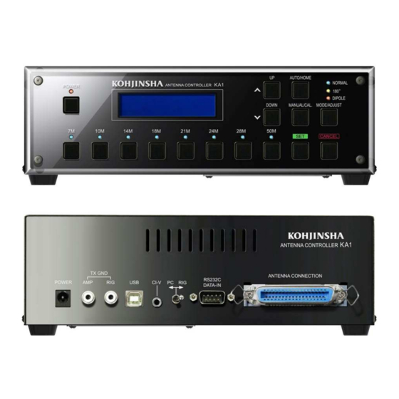
4.Controller Front Panel Buttons and Functions ■Button Names Figure 2 ① POWER Press to power ON. LED comes to light on. Press and hold to power OFF. This function is disabled during the elements in motion. One of the band LEDs comes on light when you turn power off to let you know what band position the elements have been at. - Page 6 ⑪ SET Set button for settings works like ENTER. ⑫ MANUAL/CAL. * MANUAL: For you to adjust manually. * CAL: CALIBRATION (Press and Hold); Elements moves to HOME position once and then extend to the set frequency position. ⑬ CANCEL Cancel the immediate command selection.
-
Page 7: Power Button
.Detail Functions of Front Panel Controls ■4-1 ①POWER Button Press the POWER button to power on the controller. Then Model Number, Software Version, ROM Version, and Available Frequencies are shown. The previous settings and the band will be shown some seconds later. Refer to Figure 3 and 4. - Page 8 □Freq Region Display (While Manual Mode is selected) ② 7M : 7.000-7.039MHz/7.040-7.079MHz/7.120-7.159MHz ③ 10M:10.100-10.149MHz ④ 14M:14.050-14.099MHz/14.150-14.199MHz/14.250-14.299MHz ⑤ 18M:18.100-18.149MHz ⑥ 21M: 21.050-21.099MHz/21.200-21.249MHz/21.350-21.399MHz ⑦ 24M: 24.950-24.999MHz ⑧ 28M: 28.000-28.049MHz/28.500-28.549MHz/29.000-29.049MHz ⑨ 50M: 50.100-50.149MHz *②7MHz band and ③10MHz band are not available for Model 203/204/205/206 □Freq Region Display(While Auto Mode is selected)...
- Page 9 How to Change Frequency Display Format * Go to 「User Mode」to switch frequency display format. We would like you to read 8-2 for more detail. ① Press and Hold the POWER button to turn off the power. →②Press and holding the 7M button, press POWER button. →“...
-
Page 10: Up/Down Button
*AUTO・MANUAL mode function You can obtain factory default setting status by press and hold the BAND button. If you do this operation in certain segment of a band, other segments in the same band will get to factory default. See Figure 9 and 10 Figure 9: Figure 10: In Manual mode. -
Page 11: Cancel
*CAL. (CALIBRATION)button(Press and Hold) You can start calibration on any band and in either MANUAL or AUTO mode. You will see Figure 11 by press and hold CAL button. Press ⑪SET button while [Push SET] is blinking. Then you will see Figure 12. The controller is set to factory default, which means the antenna was once calibrated under certain condition in the factory. -
Page 12: Mode/Adjust
■4-7 ⑭MODE/ADJUST button *MODE Switching NORMAL, 180°, and DIPOLE. Each time pressing this button the MODE LED blinks. During blinking elements are moving in the glass-fiber poles. When the elements are set to the length for the selected band, the LED turns on from blinking. *ADJUST (Press and hold) Your can fine tune element length. - Page 13 Figure 14: Figure 15: You will see [SET] blink if you [Push SET] is blinking. press ⑩UP or DOWN to adjust Press ⑪SET to select what AEU element. to adjust. Figure 15 shows you selected [Ra]. Figure 16 : Figure 17: Press ⑪SET to set and finish adjustment.
-
Page 14: Normal Mode
■4-8 ⑮NORMAL mode *Regular Yagi antenna mode KA1 works as regular Yagi antenna. ■4-9 ⑯180°(Reverse) mode *Front and back switch from Normal mode. Any type of KA1 works as 3 element Yagi antenna. ■4-10 ⑰DIPOLE mode *KA1 has dipole like pattern on both front and back KA1 has a little gain over dipole antenna. - Page 15 Figure 19: Figure 20: HOME [Push SET] blinks. When all the elements are retracted, Press ⑪SET button to set. the above message comes on LCD display. After showing this message the power will be shut off automatically. *While selected mode LED is blinking, elements are in motion.
-
Page 16: Rear Panel
5. Rear Panel and Connectors ■The Name of the Connectors on the Rear Panel. Figure 21 ① POWER: For AC adaptor plug. We strongly recommend you to use AC adaptor that comes with KA1. *NOTE During operation if you accidentally removed power from the controller, you should need to HOME operation (press and hold HOME and press SET) for elements to get to home position once. - Page 17 3.5mm mono mini jack. (2P) This works as same as [REMOTE] of ICOM equipment. You need to use this interface to use ICOM transceivers or KOHJINSHA linear amplifiers. ⑥ PC⇔RIG: This toggle switch lets you choose either computer or transceiver to control VERSA Beam antenna.
-
Page 18: 6. Before Start Using Ka1
6.Before Start Using KA1 ■6-1 Check and Adjust SWR at Factory Default Setting Use antenna SWR analyzer or KOHJINSHA KP-1 Power meter to measure SWR. ■6-2 Calibration The controller is set to factory default. Factory default setting is the best setting in certain condition. - Page 19 Get your tower the highest if your tower is a crank up tower. Do not do it on the day of heavy rain, snow, or windy. Choose the antenna direction to keep elements as far away as possible from trees, wires, or buildings. If the element tip is too close to those obstacles, you may not be able to obtain good SWR.
-
Page 20: How To Adjust Vswr And Save The Setting
■6-3 How to Adjust VSWR and Save the Setting SWR may not be the best at your antenna site because there should be some things that may affect your antenna at your antenna site. If you cannot get good SWR by calibration, use [Adjust] function to adjust element length. -
Page 21: Rain Mode And Snow Mode
■6-4 Rain Mode and Snow Mode The resonant frequency may move lower under rainy or snowy weather.You can use Rain Mode or Snow Mode to adjust the resonant frequency. You can adjust it manually, too. However, it should be much easier and faster to use Rain Mode or Snow Mode that can be set in advance. - Page 22 How to Set Amount of Shift Frequency No amateur radio stations should have the same place. Furthermore any antenna doesn’t have the same location. Therefore each user has to set the amount of shift frequency at each location. Move elements manually to get to the best SWR point, and measure how much frequency shift occurs on every band in each atmosphere..
-
Page 23: Checking The Element Motion
■6-5 How to Check All Elements Move Properly As described in 5-11 you can see element numbers on LCD when elements are retracted, and get to HOME position. If you see all the element numbers, AEUs work properly. If you want to check while you are using KA1, go to Adjust mode and press and hold UP or DOWN button to move elements. -
Page 24: Frequency Segment Width Change
■6-8 Frequency Segment Width Because some bands work with loading coil, low SWR( maybe below 1.5 ) range is narrower. To avoid operating with high SWR you can change the moving step width to a half of the original. 6-8-1:How to Change Stepping Frequency Segment Width for Regular VERSA Antenna (7MHz) In AUTO or MANUAL mode you can get 20KHz step by pressing and holding the DOWN button.(Figure 30 to 31) Pressing and holding UP bottun make the... -
Page 25: 7. User Mode Settings
. USER MODE Settings ■7-1 What You Can Do with USER Mode Starting with USER Mode you can set following functions. *00:Exciter Type Choose a transceiver you use with KA1. There are transceivers made by major ham manufactures that are memorized in the controller. *01:Baud Rate Select the baud rate that will be used to communicate with your transceiver. - Page 26 *07:Auto CAL You can choose No Auto CAL or Auto CAL that calibration will be done automatically when you turn on the main AC or controller power. *LCD display and its function 000: No Auto CAL ・・・・・・・No automatic calibration 001: Auto CAL ・ ・ ・ ・ ・ ・ ・ ・ ・ Calibration starts when main AC power is supplied. *08:Auto Home KA1 is designed to retract elements when the transceiver frequency is out of KA1 covering frequency.
-
Page 27: Start Your Controller With User Mode
■7-2 Start Your Controller with User Mode See Figure 32 Figure 32 Press and hold ①POWER to turn off the controller. →With Pressing and holding ②7M button, press ①POWER button. →[Figure 33 left] is shown on LCD for a while and then [Figure 33 right] appears. -
Page 28: 8. Factory Default
8. Factory Default ■Please follow the procedure written below to get back to factory default settings See Figure 34 Figure 34 Note: 1: All the elements should be retracted at home position before factory default operation. See 5-11⑱AUTO/HOME button. See Page 15 2: In order to get the factory default element length press and hold each BAND button. - Page 29 Figure 35: Figure 36: After [User mode] screen is displayed, Press and holding ②7M button press Figure 30 appears. and hold ③SET button when you see this screen. Figure 37: Figure 38: This is showing the software is getting When the work is done, you see back to factory default settings.
-
Page 30: Jumper Settings For Your Transceiver
9. Connecting with Transceivers and Computers ■9-1 Jumper Settings for Your Transceiver At this section you will learn how to set up DIP switches to connect KA-1 with your transceiver and computer. *Please look at the drawing below. Remove two screws and take off the cover. You will be able to see controller board. -
Page 31: 9-1-1.Rs232C Interface(Yaesu/Kenwood/Jrc/Elecraft)
9-1-1:YAESU/KENWOOD/JRC/ELECRAFT Transceivers ①YAESU: FTDX9000/FTDX5000/FT2000/FT1000MP/MK-V KENWOOD: TS990/TS590/TS2000/TS480/TS870 ②YAESU: FT920 ELECRAFT: K2/K3 ③JRC: JST145/JST245 *Controller interface RS232C D-sub 9pin (female) *Rig interface ①RS232C D-sub 9pin (female) ②RS232C D-sub 9pin (male) ③RS232C D-sub 25pin (male) *Set DIP switches shown as Figure 40. Figure 40 - 30 -... -
Page 32: Icom(Ci-V Interface) Transceivers
9-1-2: ICOM *All ICOM transceivers that have CI-V interface. *Controller interface: CI-V 3.5mm mini-jack (2p) *Rig interface: REMOTE 3.5mm mini-jack (2p) *Set DIP switches shown as Figure 35. Figure 41 - 31 -... -
Page 33: Yaesu: Ft1000/Ft1021
9-1-3: YAESU *Transceivers FT1000/FT1021 *Controller interface: RS232C D-sub 9pin (female) *Rig interface: DIN6 pin (male) *Set DIP switches shown as Figure 42. Figure 42. - 32 -... -
Page 34: Kenwood Ts950/Ts850
-1-4: KENWOOD *Transceivers TS950/TS850 *Controller interface: RS232C D-sub9 pin (female) *Rig interface: DIN6 pin (male) *Set DIP switches shown as Figure 43. Figure 43 - 33 -... -
Page 35: Setup With Your Computer
■9-2 Setup with Your Computer Use USB connector to connect your controller with computer. Controller has USB interface on its rear panel. ①: Unless you use logging software , turn the toggle switch(⑥PC⇔RIG) on the controller rear panel toward [RIG] side BEFORE turning power on. ②: If you use logging software , turn he toggle switch(⑥PC⇔RIG) on the controller rear panel toward [PC] side BEFORE turning power on. - Page 36 Here is more detail description for each transceiver model. Make Memory Setup Note ICOM All the Nothing n case KA1 band or frequency transceivers with jumps off and gets back to normal while you are tuning the CI-V frequency dial using with Logger 32, set the rig CI-V transceiver OFF.
-
Page 37: Memory Setting For Your Transceiver
■9-3 Memory Settings for Your Transceiver All ICOM transceivers ・ KOHJINSHA-------------------------------- 00:Exciter Type 000:KJS/ICOM 01:Baud Rate 001:1200~016:19200bps(Recommended:9600) 02:Stop bit 01:1 Stop bit YAESU---------------------------------------------------------------- FT DX 9000・FT DX 5000・FT-2000 00:Exciter Type 016:YAESU AI 01:Baud Rate 004:4800(Same baud rate as your radio interface)... -
Page 38: Memory Setting Table
■9-4 Memory Setting Table Setting items Setting Exciter Type 000 : KJS/ICOM All ICOM transceivers *KL-1 001 : MK-V 1000MP FT-1000MP,MARK-V FT-1000MP, 002 : FT-100 FT-100,FT-100D 003 : FT-920 FT-920 004 : KWD/K2/K3_IF All the transceivers after KENWOOD TS-870 and 005 : KWD/K2/K3_AI ELECRAFT *This setting is... - Page 39 Set up 00:Exciter Type 005: KWD/K2/K3_AI or 007:TS950/TS850_AI *Notice If you choose (1) to control your transceiver and VERSA Beam antenna from your computer, you need to activate your logging software. Otherwise VERSA Beam antenna doesn’t’follow your transceiver frequency. If you choose (2), your logging software can read frequency and mode from your transceiver, but you cannot control your system from your logging software.
- Page 40 000:Band&Freq Displaying [Band&Freq] on LCD *Displaying band as “m” corresponding to the transceiver frequency. If the transceiver frequency gets out of VERSA Beam coverage, “***” will be shown. However frequency is displayed as same as your transceiver frequency. 001:Freq Region Displaying [Freq Region] on LCD *Displaying frequency region all the time whatever mode is selected.
-
Page 41: 10. Trouble Shooting
10.Trouble Shooting Check Symptom Probable Cause Suggested Action Page The controller Power cable is not connected securely. Reconnect power cable. will not power up after connecting a DC power supply and Pressing [POWER]. Elements don’t Each junction cable is not connected Check connections and move. -
Page 42: 11. Command Table
11. Command Table 項目 BUTTON Page&Section Additional BUTTON Info Power on Press POWER P6・P8 5-1 Press and hold button POWER button also works Power off Press and hold POWER button Antenna band change Press band P6・P8 5-2 (When MANUL is button selected)... - Page 43 Change controller You need to Press SET settings 00~08 perform 12 first Getting factory default You need to Press and hold The set value is on controller settings00 perform 12 firs written in the ~08 ROM by press and holding Change frequency You need to 05:FreqDisp...
-
Page 44: 12. Maintenance
Service If it is ever necessary to return VERSA Beam antenna, double check by yourself or consult a Kohjinsha specialist to make sure what part of VERSA Beam antenna is wrong specifically? Then you can avoid shipping whole stuff to our factory.
Need help?
Do you have a question about the VERSA Beam and is the answer not in the manual?
Questions and answers