
Summary of Contents for Opentech INSOMNIAC CIA
- Page 1 INSOMNIAC CIA Individual Unit Alarm Installation Manual P/N CIA-A96 Revision 2 Date Code: 1-22-2020...
-
Page 2: Specifications
CIA Individual Unit Alarm Installation Manual Rev 2 SPECIFICATIONS: ESCRIPTION EATURES NCLOSURE NDOOR UTDOOR LUMINUM OWER OATED RS485 (900 MH OMMUNICATIONS IRELESS -C R ELAY UTPUTS ECURE OMMUNICATIONS AMPER 24VDC PERATING OLTAGE 12VDC PERATING OLTAGE 250 mA @ 12 VDC, 125 mA @ 24VDC NPUT URRENT 150 D... - Page 3 The wired alarm systems connects a sensor on each unit’s door to the Individual Unit Alarm Board. This allows the INSOMNIAC CIA system to monitor when the door is opened or closed. When a visitor enters the property either via a keypad or the Storage Genie app then the alarm is disarmed. When the visitor exits the property, the alarm is re-armed.
-
Page 4: Installation
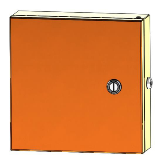
CIA Individual Unit Alarm Installation Manual Rev 2 INSTALLATION Physical Installation and Mounting This document contains instruction on installing the INSOMNIC CIA Individual Unit alarm system. Figure 1... - Page 5 CIA Individual Unit Alarm Installation Manual Rev 2 Mount the back plate to the desired location using the 4 holes in the back pane. If the enclosure is being mounted on a wall, before mounting, run a bead of silicone in a square around the back of the enclosure about ½...
- Page 6 CIA Individual Unit Alarm Installation Manual Rev 2 Pull the necessary wires through the wire hole on the back of the housing. Allow ample wire to remain inside the housing. After the wire connections are complete, excess wire can be pushed back into the wall or it can be carefully positioned inside the housing for future maintenance and service.
- Page 7 CIA Individual Unit Alarm Installation Manual Rev 2 Wiring Connections Below is a connection diagram for the Unit Alarm Printed Circuit Board (PCB). Note: All installations must conform to local building and electrical codes and shall be in accordance with the Nation Electric Code, ANSI/NFPA 70.
- Page 8 CIA Individual Unit Alarm Installation Manual Rev 2 UNIT DOOR ALARM PUNCH DOWN CONNECTORS There are six punch down connectors on the right side of the circuit board for connecting up to 96 individual unit switches. These connectors are used to connect to the individual unit alarm switches that are installed on the unit doors.
-
Page 9: Door Switches
CIA Individual Unit Alarm Installation Manual Rev 2 The wires for each door switch should be punched down on the terminal strip using the proper tool. Recommend punch down tool is .156 inch IDC T handle. Do not use a telephone punch down tool or screwdriver. - Page 10 CIA Individual Unit Alarm Installation Manual Rev 2 To connect a switch to the Unit Alarm (Trunk) Cable. Cut lengthwise into the Unit Alarm Cable approximately 3” into the outer installation and expose the individual wires. Exercise caution to not cut or damage the individual wires. Connect the two wires coming from the switch to the Unit Alarm Cable using UG style connectors to the proper wires.
- Page 11 CIA Individual Unit Alarm Installation Manual Rev 2 PWR/RS485 Power and RS485 data communication is done with a single connector and should be the last connector to be attached as it may carry active power. We recommend that power and RS485 data communications be via a single 18 AWG, 4-conductor shielded cable.
-
Page 12: Relay Contact Ratings
CIA Individual Unit Alarm Installation Manual Rev 2 Wireless Communications (Optional) The Individual Unit Alarm can also function without the RS485 wiring. In this case, the XBEE or XBEE Pro wireless module and an RPSMA antenna must be installed on the Gateway and on the Individual Unit Alarm Board. - Page 13 CIA Individual Unit Alarm Installation Manual Rev 2 Testing / Troubleshooting Each Unit Alarm input has an LED that will be on when the unit door is closed. Check the 3 Power LEDs on the PCB. If they are all dark, check / replace the PCB fuse. If any single specific power LED such as the 3.3V or 5V LEDs are dark, replace the PCB.
- Page 14 CIA Individual Unit Alarm Installation Manual Rev 2 Individual Unit Alarm Connection Worksheet Use the worksheet below to document the wire colors used for each unit switch. The Switch and Gnd/Cmn columns should be used to document the wire color that the switch is connected to. Channel Unit Switch...
- Page 15 To speed configuration of the system, the INSOMNIAC CIA has the ability to import the unit/mux/channel configurations from a PTI or StorLogix system. In order for this to be accomplished, it is required to perform an export from the PTI Falcon 2000 or StorLogix software to export the alarm.alm from StorLogix,...
- Page 16 If the current system is not operational, then it is recommended that these issues are corrected before proceeding. To speed configuration of the system the INSOMNIAC CIA has the ability to import the unit/mux/channel configurations a CSV file.
- Page 17 CIA Individual Unit Alarm Installation Manual Rev 2 5. Disconnect the RS-485 power connector from the circuit board. Label each wire DC+, DC-, Data +, Com and Data – 6. Remove the DigiGate UniMux from the building wall. 7. Install the new CIA-A96 enclosure to the wall. Pulling the existing data communication, relay and unit alarm wires into the new enclosure.
Need help?
Do you have a question about the INSOMNIAC CIA and is the answer not in the manual?
Questions and answers