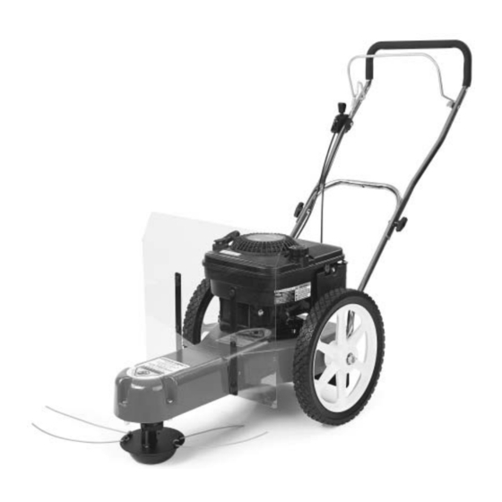
Summary of Contents for Country Home Products DR TRIMMER/MOWER SPRINT
- Page 1 ® ™ TRIMMER/MOWER Assembly & Operating Instructions ® Model: • SPRINT Please read these instructions and the Engine Manufacturer's Owner's Manual before ® ™ you assemble and use your DR TRIMMER/MOWER...
- Page 3 Thanks once again! for all of us at... ® COUNTRY HOME PRODUCTS ® ™ TRIMMER/MOWER Assembly & Operating Instructions...
- Page 4 ® ™ TRIMMER/MOWER Assembly & Operating Instructions...
-
Page 5: Table Of Contents
Table of Contents SAFETY INSTRUCTIONS ...............................1 Dress Appropriately.................................1 Preparation..................................1 Operating the Machine Safely ............................1 Safety with Gas-Powered Machines ..........................2 Warning to All California and Other Users ........................2 TRIMMER PARTS & COMPONENTS ..........................3 ASSEMBLY COMPONENTS............................4 ASSEMBLY ..................................5 CONTROLS & FEATURES ............................10 STARTING &... -
Page 7: Safety Instructions
Safety Instructions ® ™ We want you to enjoy years of productive use from your DR TRIMMER/MOWER . We don't want you to get injured, so please take a few moments to read the following guidelines for safely operating your new machine. Dress Appropriately ·... -
Page 8: Safety With Gas-Powered Machines
· ® ™ As with any trimmer, the tips of the cutting cords on the DR TRIMMER/MOWER can throw sticks, small stones, gravel, and bits of debris for long distances at great velocity. The faster the cutting cords are spinning, the farther debris may be thrown. Do not move over loose materials such as gravel or mulch with the trimmer head spinning. -
Page 9: Trimmer Parts & Components
Trimmer Parts & Components ® ™ The following parts and assembly components should be in your DR TRIMMER/MOWER package. Please check your shipping box(es) and parts package(s) for the items listed below. If your shipment is incomplete or if you have any questions, please call us TOLL-FREE 1(800)DR- OWNER (376-9637). -
Page 10: Assembly Components
Assembly Components Figure 1 ® ™ TRIMMER/MOWER Assembly & Operating Instructions... -
Page 11: Assembly
Assembly WARNING: Do not attempt to start the engine until all assembly steps are complete, and you have ADDED GAS AND OIL to the engine. Please Note: Your trimmer may look WARNING! slightly different than some of the photos shown in this manual. THIS MACHINE IS SHIPPED WITHOUT OIL! TRACES OF OIL MAY BE LEFT IN THE RESERVOIR FROM FACTORY... - Page 12 4. Insert the axle through the hole in the bushing in the side of the housing (Figure 5). Push the axle through both axle holes in the frame (Figure 5). Be sure the axle is over the black control cable. 5.
- Page 13 Step 4: Install the Handlebars A) Lower Handlebar Note: There are 2 U-bolts, 4 washers, and 4 lock nuts in your parts bag that will be needed for the lower handlebar assembly. 1. With the control cables on the inside of the handlebars, position the lower handlebar over the bolt holes in the trimmer frame (Figure 8).
- Page 14 To adjust the height of the handlebars, loosen the lock nuts on the U-bolts. Push the handlebars forward for more height, backward for less. Then tighten the nuts securely. Step 5: Attach the Acrylic Engine Shield Use the four remaining sets of 5/8" long bolts and lock nuts to attach the acrylic engine shield.
- Page 15 Step 9: Connect the Battery Wires (Electric-Starting models only) To prevent the battery from discharging during shipment, all electric-starting trimmers are shipped with the black, negative battery wire disconnected. Connect the two black wires by pushing the plastic ends together (Figure 12). See the red wires for comparison.
-
Page 16: Controls & Features
Controls & Features Please Note: Manual-Starting Model shown. Figure 13 ® ™ TRIMMER/MOWER Assembly & Operating Instructions... -
Page 17: Starting & Operating
Starting & Operating WARNING! THIS MACHINE IS SHIPPED WITHOUT OIL! TRACES OF OIL MAY BE LEFT IN THE RESERVOIR FROM FACTORY TESTING, BUT YOU MUST ADD THE RECOMMENDED AMOUNT OF OIL BEFORE STARTING THE ENGINE. Please Note: Manual-Starting model is pictured below. Electric-Starting 1. -
Page 18: Stopping The Engine
Stopping the Engine Move the throttle lever back to the STOP position (Figure 13). Note that on Electric-Starting Models the key does not stop the engine. The key has a pressure lock that prevents it from vibrating loose during operation. If you wish to remove the key, push it in and then quickly and firmly pull it ®... -
Page 19: Cutting Cords
Cutting Cords WARNING: Turn the engine off when installing or changing cutting cords. Two thicknesses of cutting cord ship with your ® ™ TRIMMER/MOWER : Heavy-duty (130 mil) Orange and Extra Heavy-duty (155 mil) Green. Figure 15 shows how the cords are installed at the factory. -
Page 20: Trimming And Mowing Methods
Trimming and Mowing Methods The cutting cords cut one to two inches Note: outside of the wheel width. Many owners like to mow easy, open areas with their regular riding or walk-behind mower, then finish trimming all the odd and ®...


Need help?
Do you have a question about the DR TRIMMER/MOWER SPRINT and is the answer not in the manual?
Questions and answers