Table of Contents
Advertisement
Quick Links
Advertisement
Table of Contents

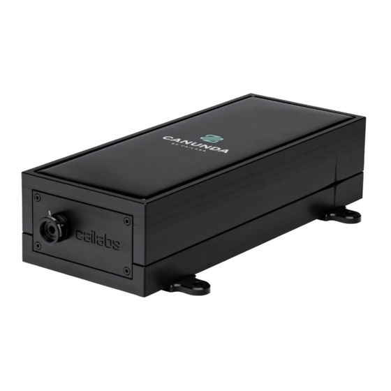
Summary of Contents for Cailabs CANUNDA-PULSE
- Page 1 INSTALLATION MANUAL 2020/12...
-
Page 3: Table Of Contents
Table of contents 1. Safety ............................. 4 2. Recommended equipment for installation ..................4 3. Installation ............................. 5 3.1 Module preparation ..............................5 3.2 Beam preparation ............................... 5 3.3 Module positioning ..............................6 3.4 Module insertion ................................7 3.5 Power optimization ..............................8 3.6 Beam shape verification ............................. -
Page 4: Safety
1. Safety Beware of the risks involved when working with your laser. Check your laser eye safety class and follow the recommendations. Follow the guidelines provided by the manufacturer of your laser source. 2. Recommended equipment for installation • Pedestals •... -
Page 5: Installation
The module input is 35 mm above the bottom surface of the choose and install the appropriate pedestals to elevate the module mounting brackets. The beam height H is then related CANUNDA-PULSE module at the correct working height. to pedestals height H +35 mm Example: With 50 mm pedestals, the beam height H is 85 mm 3.2 Beam preparation... -
Page 6: Module Positioning
3.3 Module positioning Equipment needed: • CANUNDA-PULSE Module with pedestal installed. • Graduated ruler • Rail The front surface of the module must be located 60 mm before the beam waist position, as depicted in the picture below. After locating the beam waist position, determine the the rail is as close as possible to either the front or the back expected longitudinal position of the module. -
Page 7: Module Insertion
Remove the input and output protective caps of the (alternatively, an IR viewer can be used along with a piece of CANUNDA-PULSE module and set the module’s input iris at white paper as a diffusor). Open the input iris, light should come minimal aperture. -
Page 8: Power Optimization
3.5 Power optimization Equipment needed: • Power meter Position a power meter at the module output and optimize mount, in order to have maximum transmission (see picture output power by manipulating the last mirror’s kinematic below). Be careful as you might encounter a local maximum. To make Fine tune the optimization using both mirrors horizontally and sure you find the position of the maximum power, do half a vertically. -
Page 9: Beam Shape Verification
3.6 Beam shape verification Equipment needed: • Beam profiler or camera Position a beam profiler or a camera directly at the module If the beam shape does not match the specifications, the power output (see picture below). Check the beam shape 20 mm after optimization of the previous step may have been set to a local the back surface of the module. - Page 10 CA ILA B S 38 boulevard Albert 1er 35200 Rennes, France www.cailabs.com contact@cailabs.com @CAILabs...
Need help?
Do you have a question about the CANUNDA-PULSE and is the answer not in the manual?
Questions and answers